Download
1 / 40
400 likes | 627 Views
Local Illumination and Shading. Computer Graphics – Lecture 10 Taku Komura tkomura@inf.ed.ac.uk Institute for Perception, Action & Behaviour. Last Lecture… . Hidden Surface Removal Back face culling Painter’s algorithm BSP Tree Z-buffer.

E N D
Local Illumination and Shading Computer Graphics – Lecture 10 Taku Komura tkomura@inf.ed.ac.uk Institute for Perception, Action & Behaviour
Last Lecture… • Hidden Surface Removal • Back face culling • Painter’s algorithm • BSP Tree • Z-buffer
Back Face CullingLight(L), view (V), and normal(N) Cull faces according to L.N and V.N Cull if V.N < 0 Cull if L.N > 0 (if only one light, and no ambient light)
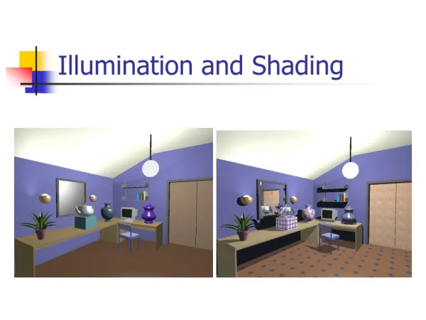
Today is about calculating the color of objects The incident light • Position of light source • Direction • Color The object • Reflectance Viewer • Position
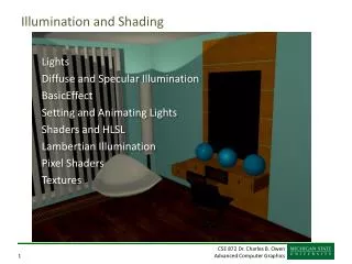
Overview • Illumination (how to calculate the color) • Shading (how to color the whole surface)? • BRDF (how to simulate the reflection of real objects)
Object Illumination • Simple 3 parameter model • The sum of 3 illumination terms: • Ambient : 'background' illumination • Specular : bright, shiny reflections • Diffuse : non-shiny illumination and shadows surface normal (specifies surface orientation) Light source (here point light source) 'Virtual' camera
Ambient Lighting • Light from the environment • light reflected or scattered from other objects • simple approximation to complex 'real-world' process • Result: globally uniform colour for object • I = resulting intensity • Ia= light intensity • ka = reflectance Example: sphere N I Uniform Light source Object camera
Object Diffuse Lighting • Also known as Lambertian reflection • considers the angle of incidence of light on surface (angle between light and surface normal) • Result: lighting varies over surface with orientation to light Ln Infinite point light source Example: sphere (lit from left) N I No dependence on camera angle!
Object Specular Lighting • Direct reflections of light source off shiny object • specular intensity n = shiny reflectance of object • Result: specular highlight on object Ln N Infinite point light source R (Reflection) α I= output color Rn= camera position α : angle between Rn and S No dependence on object colour.
Combined Lighting Models • Summing it altogether : Phong Illumination Model = + + Rc Specular (highlights) Ambient (colour) Diffuse (directional)
Object When you implement it… Use dot product of the vectors instead of calculating the angles N Ln R α V : Vector from the surface to the viewer : Normal vector at the colored point : Reflection vector : Vector from the light source towards the colored point
Color • You do the above computation for Red, Green and Blue color • Finally color the pixel by the RGB color
Demo applets • http://www.cs.unc.edu/%7Eclark/courses/comp14-spr04/code/SphereLightApplet.html • http://www.cs.auckland.ac.nz/~richard/research-topics/PhongApplet/PhongDemoApplet.html
Overview • Illumination (how to calculate the color) • Shading (how to color the whole surface)?
How often do we do the computation of illumination? • At all the points on the surface? • But usually we have normals only at the vertices Depends on the shading model – Flat Shading (once per polygon) (less computation needed) – Gouraud shading (for all the vertices of the polygon) – Phong Shading (all the points) (heavy computation needed)
Flat Shading • Compute the color at the middle of the polygon • All points in the same polygon are colored bythe same color
Gouraud Shading (Smooth Shading) • Compute the color at each vertex first • Compute the color inside the polygon by interpolating thecolors of the vertices composing the polygon
Phong Shading • interpolating the normal vectors at the vertices • Do the computation of illumination at each point in thepolygon
Gouraud Shaded Floor Phong Shaded Floor • Gouraud shading is not good when the polygon count is low
Phong Shading • interpolating the normal vectors at the vertices • Do the computation of illumination at each point in thepolygon
A C B Problems with interpolation shading. • Problems with computing vertex normals. A,B are shared by all polygons, but C is not shared by the polygon on the left. • Shading information calculated to the right of C will be different from that to the left. • Shading discontinuity. Solution : ?
Problems with interpolation shading. • Problems with computing vertex normals. Face surface normals and averaged vertex normals shown. Solution:?
Exercise • Draw a picture by Phong Shading by enhancing the demo program I put up on the web. • When doing the rasterization, you do the computation of the illumination
Overview • Illumination (how to calculate the color) • Shading (how to color the whole surface)? • BRDF (how to simulate the reflection of real objects)
What about real objects? • Phong Illumination model is popular but actually it is not accurate • True photorealism, requires more sophisticated and elaborate models of surface properties
Reflectance of objects • The way the light reflects depends on the physical characteristics of the surface • Its not uniform
Bidirectional Reflectance Distribution Function (BRDF) • The reflectance of an object can be represented by a function of the incident and reflected angles • This function is called the Bidirectional Reflectance Distribution Function (BRDF) • where E is the incoming irradianceand L is the reflected radiance
What affects the BRDF? • The way light reflecting over the surface • The smoothness/roughness of the surface • Single reflection : if smooth, specular • Multiple reflections : diffusive • The shadowing effect
Isotropic and Anisotropic BRDFs • Isotropic: • Can model by diffuse + specular reflection • Anisotripic • Brushed metal • Cannot model by diffuse + specular reflection
How to get the BRDF? • Measure Data • Use Analytical models • Empirical models • Microfacet
Measuring the BRDF • Measured using a device called gonioreflectometer • Casting light from various directions to the object, and capturing the light reflected back
Problems with Measured BRDF • Includes a lot of error • Huge amount of time to capture • The data size is enormous • 18 hours acquisition time, 30GB raw data • Ngan et al. EGSR ’05 -> Fitting the acquired data into analytical models
Analytical models • Empirical models • Gouraud, Phong models or more complex models • Microfacet models • Assuming the surface is composed of a large number of micro mirrors • Each reflect light back to the specular direction
Microfacet Theory • [Torrance & Sparrow 1967] • Surface modeled by tiny mirrors • Value of BRDF at • # of mirrors oriented halfway between and where is the incoming direction, is the out going direction • Modulated by Fresnel, shadowing/masking [Shirley 97]
Summary • Illumination model • Phong model • Shading • Flat, • Gouraud, • Phong Shading • BRDF • Measuring • Analytical models • Phong • Microfacet