Download
1 / 27
270 likes | 294 Views
Understand how to produce electrical current using Faraday's Law of E&M Induction through observations and experiments. Explore the concepts of magnetic flux, induced EMF, and the relationship between magnetic field and motion.

E N D
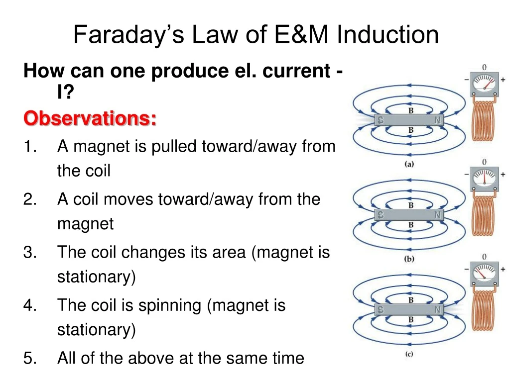
Faraday’s Law of E&M Induction How can one produce el. current - I? Observations: • A magnet is pulled toward/away from the coil • A coil moves toward/away from the magnet • The coil changes its area (magnet is stationary) • The coil is spinning (magnet is stationary) • All of the above at the same time
--- v +++ As we do this, using F=qvxB we find that the positive charges will be pushed down the wire and negative charges will be pushed up the wire. · · · · · · · · · · · · · · · · · · · · · · · · · · · · · · · · · · · · · · · · · · · · · · · · · · · · · · · · · · · · · · · · · · · · · · · · Let’s pull the above wire through a B-field with a constant velocity as shown.
v --- FBD of a single + charge · · · · · · · · · · · · qE · · · · · · · · · · · · · · · · · · · · · · · · · · · · · · · · · · · · + · · · · · · · · · · · · · · · · · · · · · · · · +++ qvB Let’s take a look at the + charges. The Forces on a + charge above will be: Fmag = qvB Felectric = qE The balance happens when E = vB.
The Voltage across the top of the wire and the bottom of the wire will be: Vwire = ELwire FBD of a single + charge qE + qvB The balance happens when E = vB. Thus: V = vLB
33.2 The Earth’s Magnetic field strength is 50 T. How fast would you have to drive your car to create a 1.0V motional emf along your 1.0m long radio antenna? (You can assume that the motion to the antenna is perpendicular to B.) V = vLB
Magnetic Flux In order to describe our model we need to introduce the concept of MAGNETIC FLUX Magnetic flux represents the number of magnetic field lines going through the loop. The Unit of FB is Tm2 (Weber =1Tx1m2).
· · · · · · · · · · · · · · · · · · · · · · · · C B A · · · · · · · · · · · · · · · · · · · · · · · · · · · · · · · · · · · · · · · · · · · · · · · · Each of these three loops is moving with a constant velocity to the right. What can you tell me about the current in each loop?
Which direction does the current travel? • Clockwise • Counter-Clockwise • There is no current. · · · · · · · · · · · · · · · · · · · · · · · · C B A · · · · · · · · · · · · · · · · · · · · · · · · · · · · · · · · · · · · · · · · · · · · · · · ·
Finger PRS: Magnetic Flux You measure the magnetic flux through the surface of a closed loop to be zero (FB=0), then you conclude that: • There is no magnetic field in space. • Magnetic field lines are perpendicular to the surface of the loop. • Magnetic field lines are parallel to the surface of the loop. • The effective area of the loop is zero. • Statements 1,3,4 can be true. • Statements 1,2, 3,4 can be true.
Faraday’s Law of EM Induction Induced EMF (e) is proportional to the rate of change of the magnetic flux through the coil and to the number of loops in the coil. The minus sign means that the induced EMF opposes to the change of the magnetic flux. This law has been tested over and over again in the labs and at your homes… It has more applications that you might think of…
Faraday’s Law of EM Induction: Testing Moving conducting rod changes the effective area of the loop and consequently changes the magnetic flux. As the result the induced EMF will be created which will be indicated by the bulb!
B · · · · · · · · · · · · Va = 2cm/s Vb = 4cm/s Vc = 2cm/s Vd = 2cm/s A F H · · · · · · · · · · · · E · · · · · · · · · · · · · · · · · · · · · · · · G D C · · · · · · · · · · · · · · · · · · · · · · · · Each loop of conductive wire is moving to the right at the constant velocity listed. Each loop is either 25%, 50%, 75% or 100% inside the indicated B-field. Loop H is half of the size of the others. Rank in order in the induced current in each of the loops at the time and position indicated. Ve = 0cm/s Vf = 2cm/s Vg = 4cm/s Vh = 4cm/s
What best describes the magnitude of the induced currents in loop H and D? · · · · · · · · · · · · • IH > ID • IH < ID • IH = ID H · · · · · · · · · · · · · · · · · · · · · · · · · · · · · · · · · · · · D · · · · · · · · · · · · · · · · · · · · · · · · Each loop is moving to the right with: Vd = 2cm/s Vh = 4cm/s
Enter question text... • Enter answer text...
Va = 2cm/s Vb = 4cm/s Vc = 2cm/s Vd = 2cm/s · · · · · · · · · · · · H · · · · · · · · · · · · · · · · · · · · · · · · · · · · · · · · · · · · D · · · · · · · · · · · · Ve = 0cm/s Vf = 2cm/s Vg = 4cm/s Vh = 4cm/s · · · · · · · · · · · · IH > ID IH < ID IH = ID
Va = 2cm/s Vb = 4cm/s Vc = 2cm/s Vd = 2cm/s B · · · · · · · · · · · · A F H · · · · · · · · · · · · E · · · · · · · · · · · · · · · · · · · · · · · · G D C · · · · · · · · · · · · Ve = 0cm/s Vf = 2cm/s Vg = 4cm/s Vh = 4cm/s · · · · · · · · · · · · Each loop of conductive wire is moving to the right at the constant velocity listed below. Each loop is either 25%, 50%, 75% or 100% inside the indicated B-field. Loop H is half of the size of the others. Rank in order in the induced current in each of the loops at the time and position indicated.
33.41 A small, 1.50-mm-diameter circular loop with R = 1.40×10⁻² Ohms is at the center of a large 120-mm-diameter circular loop. Both loops lie in the same plane. The current in the outer loop changes from +1A to -1A in 9.00×10⁻² sec . What is the induced current in the inner loop? • Which way does I induced go? • What about after the 90 ms? • Do we use A or a in this problem? Remember: Bcoilcenter = oI/(2R)
33.49 The figure shows a U-shaped conducting rail that is oriented vertically in a horizontal magnetic field. The rail has no electric resistance and does not move. A slide wire with mass mand resistance R can slide up and down without friction while maintaining electrical contact with the rail. The slide wire is released from rest. Determine the value of a terminal velocity if l = 21.0cm , m = 7.00 g, R = 8.00×10⁻² Ohms, and B = 0.540 T .
Some good sample problems: 34.51 34.52
Initially, in which direction does the current flow through the light bulb? • To the right • To the left • There is no current.
Lenz’s Law (an application of a Faraday’s Law of EM induction) An induced current always flows in a direction that opposes the change that causes it! The magnet is pulled away from the ring!
Some Applications of Induced Currents: Generators:
Some Applications of Induced Currents: Transformers
Some Applications of Induced Currents: Electronics -- Inductors A coil of wire is going to have a self-inductance. This self-inductance is defined as: As in a capacitor, L is dependent upon the geometry and construction of the coil of wire.
Going back to Faraday’s Law: and since: we get: Or, as part of a circuit
The three main topics covered in this chapter are: • We observed that moving magnets create currents in loops of wire. • We calculated that a long straight wire traveling (perpendicular) through a magnetic field has an induced voltage from the “top” to the “bottom” of the wire. • We found that for loops of wire: • + LC Circuits


