Download
1 / 61
610 likes | 637 Views
Explore secondary beam detection methods including Cherenkov, Scintillation, and Ionization detectors. Learn about the CEDAR system for particle identification in experimental areas.

E N D
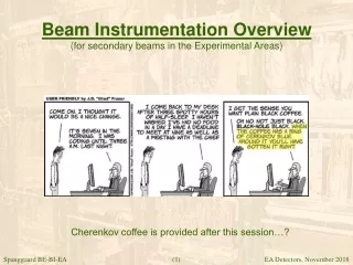
Beam Instrumentation Overview(for secondary beams in the Experimental Areas) Cherenkov coffee is provided after this session…? (1)
Beam Instrumentation Overview(for secondary beams in the Experimental Areas) Slides covering: • EA - Detectors based on Cherenkov light • EA - Detectors based on Scintillation • EA - Detectors based on Ionization (2)
How to detect interaction with matter(matter only allowed on secondary beam lines :o) • Charged particles interact with matter and lose energy to the medium: • By Excitation, Ionization, Bremsstrahlung and Cherenkov radiation. • Energy is mainly lost due to interaction with the electrons of the atoms or molecules of the medium. • In order to detect this we need the energy-loss to be made visible in the form of light or electrical charge collection. (3)
Cherenkov Effect(i) Experimentally observed by Cherenkov in 1934 Theoretical explained by Frank & Tamm in 1937. (4)
Cherenkov Effect(ii) Cherenkov light in an atomic reactor (5)
Cherenkov Effect(iii) • The Cerenkov effect occurs when the velocity of a charged particle traveling through a dielectric medium exceeds the speed of light in that medium. Cherenkov light is produced when v > c/n where n is the refraction index (6)
Cherenkov Effect(iv) v < c/n v > c/n Local polarization by a slow particle - and a relativistic particle (7)
Threshold Cherenkov Counter(XCET) Threshold Cherenkov Counter followed by a Scintillation Counter. (each equipped with a PMT) (9)
Threshold Counter(ii) mirror beam gas control PM • The Threshold Cherenkov Counter (TCC) is basically a gas tank with a photomultiplier. • A pulse is produced only from particles that are above the Cherenkov threshold. • Pressure regulation allow to adjust the threshold level. (10)
Threshold Counter(particle identification) mirror mirror pion, kaon, proton n2 n1 beam C1 C2 gas control gas control PM PM (11)
Threshold Counter(computed response) Choice of gas and pressure for identifying particles. (all particles to the left of a chosen gas/pressure will be detected) (12)
The CEDAR(XCED) A CEDAR with its pneumatic pressure control unit. (13)
The CEDAR(ii) • The CErenkov Differential counters with Achromatic Ring focus, CEDAR, were build at CERN in 1982 for identification and selection of particles in the secondary beams of the SPS experimental areas. • https://cds.cern.ch/record/142935/files/CERN-82-13.pdf • Unlike a Threshold Counter, the CEDAR can be tuned to flag only protons, only kaons, only pions, only muons or only electrons. (14)
The CEDAR(schematic principle) gas tank 6-, 7- and 8-fold coincidence are recorded (8 PMTs) (15)
The CEDAR(iv) (16)
The CEDAR(tuning) pion ring Kaon ring Proton ring Diaphragm opening Alignment Diaphragm opening CEDAR-flight-through (17)
The CEDAR(alignment) • curves (18)
The CEDAR(Pressure Scan) • curves (19)
The CEDAR(viii) • CEDARs were designed to validate the composition of particles for different beam settings. • Nowadays both CEDAR and threshold counter are often an integral part of the triggering system of an experiment… • ..which in turn vehicle good relations between BI and the end user :o) (20)
Outlook() • Experiment NA62 has upgraded a CEDAR for high beamrate 800MHz: • Replacement of 8 PMT with thousand Si-photodetectors. A CEDAR with its 8 PMTs (22)
Beam Instrumentation Overview(for secondary beams in the Experimental Areas) Slides covering: • EA - Detectors based on Cherenkov light • XCET, XCED • EA - Detectors based on Scintillation • EA - Detectors based on Ionization (23)
Scintillation and Scintillators(i) • Scintillation is emission of photons following excitation of atoms or molecules by radiation • Fluorescence: Prompt emission of photons (<10 ns) after absorbing electromagnetic radiation (energy). • Phosphorescence: Slow ongoing emission of photons (ms to hours) after absorbing electromagnetic radiation (energy). • Several complex excitation states are possible in molecules but basically we are talking about electrons returning to a more stable energy level after excitation. (24)
Scintillation and Scintillators(mechanisms of scintillation) • Gaseous Scintillators • De-excitation of electrons in single atoms excited by the passage of an incoming particle. Most noble cases can be used. • Plastic/organic Scintillators • De-excitation of free valence electrons in more complex molecules which are often doped with impurities. Examples and NE102 (plastic) and Naphthalene or Anthracene (crystals). • Inorganic Scintillators • De-excitation of the special electronic band structure found in certain inorganic crystals. Typical examples are Sodium Iodide (NaI) and Bismuth Germanium Oxide (BGO). (25)
Scintillation and Scintillators(good scintillator properties) • Efficient in converting exciting energy into light. • Transparent to its florescent radiation (photons). • Fast, with a short decay constant (florescence rather than phosphorescence). • Radiation hard. • Emitting light with a wavelength that can easily be detected. • Easy (cheap) to produce. (26)
Photo-Multiplier Tube() Secondary emission amplification (several million times). (27)
The Scintillation Counter(XSCI) Typical scintillation counter for particle physics. (28)
Use of Pulse Height Analysis(i) PM PHA Regrouping PM pulses with the same amplitude (29)
Use of Pulse Height Analysis(ii) First Ion-species from the 2011 run seen on the H8 beam line for UA9. Pulse Height Analysis on XSCI.042.475 Time: MD on 11/11-11 at 01:17 AM BE-BI Pb82 Fragments PM PHA (30)
Use of Pulse Height Analysis(iii) Ion fragments on the H2 Pulse Height Analysis on XSCI.021.528 Time: November 22nd 2011 at 13:11 BE-BI Pb82 Fragments PM PHA (31)
Outlook(XBPF) • Scintillating fiber profile monitors have this year been installed with success for the Neutrino Platform. • Our doctoral student, Inaki Ortega Ruiz has written his PhD on these new detectors :o) (35)
Beam Instrumentation Overview(for secondary beams in the Experimental Areas) Slides covering: • EA - Detectors based on Cherenkov light • XCET, XCED • EA - Detectors based on Scintillation • XSCI, XFFH, XFFV, XBPF • EA - Detectors based on Ionization (36)
Geiger-Müller History(i) Hans Geiger (left) was Rutherford's main partner in alpha-ray research and in 1908 he used an electrometer to demonstrate the passage of an alpha particle (37)
Geiger-Müller History(ii) Walther Müller, a young PhD student of Hans Geiger, improved the method and together they refined the Geiger-Müller counter back in 1928. (38)
Geiger-Müller Counter(working principle) Chain reaction and avalanche effect throughout a Geiger Müller tube (after a single primary ionization!) (39)
Geiger-Müller Counters() Different Geiger-Müller Counters (dosimeters) (40)
Charpak’s MWPC(iii) Georges Charpak invented the MWPC at CERN in 1968 For which he got the Nobel Prize in 1992 (41)
Ionization Detectors(i) Ionization Free electron Free electron + Charged Ions + Charged Ion (heavy) Free electrons moves fast towards the anode… while more heavy ions moves slowly towards the cathode to recuperate an electron. (42)
Ionization Detectors(ii) Some examples: Smoke detector MWPC Dosimeter Ionization Amplification Free electron + Charged Ions Ionization region – Proportional region – Geiger Müller region : Three different types of detectors (43)
Ionization Detectors(iii) • The simple Ionization Chamber has no gain. • The Multi-Wire Proportional Chamber (MWPC) features an avalanche amplification linearly proportional to the primary ionization. • The Geiger-Müller counter works close to sparking (Geiger-Müller region) where the voltage is sufficiently high to create secondary avalanche spreading through-out the tube. (44)
EA Ionization Chamber(XION) An Ionization Chamber upstream the COMPASS experiment (45)
EA Ionization Chamber(Schematic) + (Battery operated) Document hyperlink Ionizing particle Tank with argon gas EA Ionization Chamber for intensity measurement (10^6 to 10^10 p/s) (The Scintillation Counter typically cover 1 to 10^7 p/s) (46)
Multi-Wire Proportional Chamber(XWCA, XWCM, XWCD) MWPC and local integrators on the beam line Profiles (47)
Multi-Wire Porportional Chamber(ii) + HV Strong field lines close to the anode wires Multi-Wire Proportional Chamber (one plane) Anode wires are surrounded by cathode foils in a ArCO2 gas mixture. (48)
Multi-Wire Porportional Chamber(working principle) Argon/CO2 gas mixture + HV Field lines around anode wires Avalanche takes place in the vicinity of the thin (10 um) anode wires where the electrical field is much higher. (49)
Delay Wire Chamber(XDWC) Delay Wire Chamber on the beam line Profiles (50)