Download
1 / 74
750 likes | 948 Views
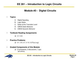
EE 261 – Introduction to Logic Circuits. Module # 3 - Digital Circuits Topics Digital Signaling Logic Gates Gates at the Transistor Level CMOS Static Behavior CMOS Dynamic Behavior Textbook Reading Assignments 3.1–3.6 Practice Problems 3.1, 3.5, 3.7, 3.13, 3.27( a,c,e,g )

E N D
EE 261 – Introduction to Logic Circuits Module #3 - Digital Circuits • Topics • Digital Signaling • Logic Gates • Gates at the Transistor Level • CMOS Static Behavior • CMOS Dynamic Behavior • Textbook Reading Assignments • 3.1–3.6 • Practice Problems • 3.1, 3.5, 3.7, 3.13, 3.27(a,c,e,g) • Graded Components of this Module • 2 homeworks, 2 discussions, 1 quiz (all online)
EE 261 – Introduction to Logic Circuits Module #3 - Digital Circuits • What you should be able to do after this module • Draw the Symbols, Equation, and Truth Table for Basic Logic Gates • Draw the transistor-level circuit of a CMOS Inverter, NAND-Gate, and NOR-Gate • Describe CMOS Logic Static Behaviors (Noise Margins, Load Current, Fan-In/Out) • Describe CMOS Logic Dynamic Behaviors (Delay, Power, SSN, ESD)
Digital Signaling • Digital Signaling- A binary number system contains two symbols and a set of operations- But what does a '0' or a '1' look like in real life?- Many things can represents 0's and 1's, but we are interested in representing them using "electrical signals" • Logic Signals- to represent a 0 or 1, we use an electrical signal (voltage or current)- let's focus on voltage to begin with
Digital Signaling • Logic Signals- a logic signal may look like this…- we define a threshold to represent when we consider the signal a: LOGIC 0 or LOGIC 1 v(t) vthreshold t
Digital Signaling • Logic Signals- we say that the signal is: LOW = when the voltage is < Vthreshold HIGH = when the voltage is > VthresholdPositive Logic : when a LOW represents a 0 when a HIGH represents a 1 Negative Logic : when a LOW represents a 1 when a HIGH represents a 0 v(t) vthreshold t
Digital Signaling • Using Positive Logic • Noise- Digital signals have an advantage when noise is present v(t) 0 1 0 1 vthreshold t v(t) 0 1 0 1 vthreshold t
Logic Gates • Logic Circuit- a circuit that produces logic outputs depending on the logic inputsex) • Combinational Logic- The outputs of the logic circuit depend ONLY on the current input values Logic
Logic Gates • Truth Table- a table that lists the output values for a given set of inputs in a logic circuit- for "n" inputs, there are 2n possible input combinationsex) n = 2In1In2Output 0 0 0 0 1 0 1 0 1 1 1 0 - when designing a logic circuit, we typically start with the truth table
0 1 Logic Gates • Logic Gates- the basic building blocks of digital logic- these represent the most simple logic operations • BUFFER Gate - Out = In
Logic Gates • NOT Gate- also called an inverter - Out = In' • AND Gate - Out = A•B = AB
Logic Gates • OR Gate- Out = A + B
Logic Gates • XOR Gate- Out = A B • NAND Gate - Out = (A•B)'
Logic Gates • NOR Gate- Out = (A + B)' • XNOR Gate - Out = (A B)'
Logic Gates • Timing Diagram- Real systems operate with respect to time- When we draw out the logic waveforms vs. time it is called a "Timing Diagram" A B Z t
Logic Gates • Simple Logic Circuits- we use the basic gates to construct more complex combinational circuits- using our notation (•, +, , ') we can write the "logic expression" for complex circuits Z = (A B) + C
Logic Gates • Delay- There is delay through each gate. In order to have a valid output, we must wait for the signals to propagate through all the gates in the circuit- this delay can be described using timing diagrams • Conversion to Truth Tables- From a circuit diagram, we can draw the timing diagram & truth table- From the truth table, we can draw the timing diagram & circuit diagram- From the timing diagram, we can draw the circuit diagram & truth table
Gates at the Transistor Level • Logic Gates- we've seen the basic logic gates that we use to form more complex logic expressions BUF, INV, AND, NAND, OR, NOR, XOR, XNOR • Logic Signaling - we've seen how we use an electrical signal to represent and transmit logic values A 0 0 1 1 1 1 0 1 1 1 B t
Gates at the Transistor Level • Logic Families- now we want to see how we actually create these circuits and signals using electronics- there are different ways (or circuits) to implement logic gates- the circuits are designed to interface with other circuits with the same type of design- a collection of IC's designed to interface with each other is called a "Logic Family"- the most common families we deal with in school are: 1) CMOS 2) TTL
Gates at the Transistor Level • MOSFET- stands for Metal Oxide Semiconductor Field Effect Transistor- there are two types of MOSFET's 1) NMOS 2) PMOS - this is analogous to bipolar transistors (npn, pnp)- a MOSFET is a 3 terminal device - this device can be thought of as a "voltage controlled resistor"- a change on the gate voltage changes the resistance between the Drain and Source- we can turn ON/OFF the flow of current by altering the voltage on the Gate Drain Gate Source
D IDS G +VGS - S Gates at the Transistor Level • NMOS- an NMOS will allow current to flow between the Drain and Source when: VGS > 0- When VGS = 0, no current flows- Cross Section of NMOS Construction Gate Source Drain Metal Oxide p n n Semiconductor
Gates at the Transistor Level • PMOS- a PMOS will allow current to flow between the Drain and Source when: VGS < 0- When VGS = 0, no current flows- Cross Section of PMOS Construction -VGS+ S IDS G D Gate Source Drain Metal Oxide n p p Semiconductor
VDD VDD D D OFF ON Logic 0 G Logic 1 G S S GND GND Gates at the Transistor Level • Basic NMOS Operation- we typically call the power supply VDD (+5v, +3.3v, +2.5v, +1.8v) - We typically call the ground either GND or VSS (0v)
Gates at the Transistor Level • Basic PMOS Operation VDD VDD S S ON OFF Logic 0 G Logic 1 G S D GND GND
VDD VDD S S VDD VDD D D ON OFF Logic 0 G Logic 1 G OFF ON Logic 0 G Logic 1 G S D S S GND GND GND GND Gates at the Transistor Level • CMOS- we now have two complementary switches PMOS NMOS
Gates at the Transistor Level • CMOS- CMOS = Complementary MOS- The complementary structure gives a way to always connect the output to either VDD or GND- Consider the following circuit VDD S G PMOS D Input Output D NMOS G S GND
Gates at the Transistor Level • CMOS- When the Input = 0, the Output is connected to VDD VDD S G PMOS=ON D Input = 0 Output=1 D NMOS=OFF G S GND
Gates at the Transistor Level • CMOS- When the Input = 1, the Output is connected to GND- this is how we construct a CMOS Inverter VDD S G PMOS=OFF D Input = 1 Output=0 D NMOS=ON G S GND
Gates at the Transistor Level • CMOS Inverter- Graphically, this looks like: VDD = HIGH Vin GND = LOW Vout t
Gates at the Transistor Level • MOSFET Level- we have two complementary switches VDD S Input = 0, PMOS = ONInput = 1, PMOS = OFF G S GND VDD D Input = 0, NMOS = OFFInput = 1, NMOS = ON G S GND
Gates at the Transistor Level • MOSFET Level- another way to draw these is as follows: VDD S Input = 0, PMOS = ONInput = 1, PMOS = OFF G S GND VDD D Input = 0, NMOS = OFFInput = 1, NMOS = ON G S GND
Gates at the Transistor Level • CMOS Gates- NMOS and PMOS transistors can be used together to form logic gates- the complementary structure is desired because the output is always being driven with a MOSFET - HIGH = a PMOS is ON and connecting the output to the VDD supply all of the NMOS's are OFF - LOW = an NMOS is ON and connecting the output to the VSS supply (GND) all of the PMOS's are OFF
Gates at the Transistor Level • CMOS InverterInput = 0Input = 1 VDD VDD PMOS = ON PMOS = OFF S S G G 1 0 S S ILOAD ILOAD 0 1 D D G G S S NMOS = OFF NMOS = ON GND GND
Gates at the Transistor Level • CMOS NAND Gate- PMOS's in parallel provide an OR'ing structure for the connection to VDD- NMOS's in series provide an AND'ing structure for the connection to GND VDD VDD A B Output A B GND
Gates at the Transistor Level • CMOS NAND Gate- We can increase the number of inputs to the NAND gate by - adding more PMOS's in parallel - adding more NMOS's in series VDD VDD A B Output A B
Gates at the Transistor Level • FAN-IN- Can we increase the number of inputs infinitely? - No, because…. - adding PMOS's in parallel decreases the ON resistance and will consume too much power - the capacitance from all of the gates on a single input line will slow down the circuit- We define "Fan-In" as the number of inputs that a given device can have ex) CMOS NAND : Fan-In = 6- the datasheet for the device will specify this
Gates at the Transistor Level • CMOS NOR Gate- PMOS's in series provide an AND'ing structure for the connection to VDD- NMOS's in parallel provide an OR'ing structure for the connection to GND VDD A B Output A B GND GND
Gates at the Transistor Level • CMOS NOR Gate- We can increase the number of inputs to the NOR gate by - adding more PMOS's in series - adding more NMOS's in parallel- Again, Fan-In applies A B Output A B GND GND
Gates at the Transistor Level • Non-Inverting Gates- What about AND, OR, and BUF? - In CMOS, we use INV, NOR, NAND for everything - BUF Gate = 2 Inverters - AND Gate = NAND and Inverter - OR Gate = NOR and Inverter
CMOS Static Behavior • Logic Levels- We need to define boundaries when the signal is considered HIGH or LOW- what is the logic level in the middle region? VDD = HIGH Vin HIGH LOW GND = LOW Vout t
CMOS Static Behavior • CMOS Static Behavior- "Static" or "DC" refers to the gate's operation when the inputs are NOT changing- also called "Steady State"- if we plotted Vout vs. Vin of an Inverter, we would get… Vout Logic HIGH Logic LOW Vin
CMOS Static Behavior • CMOS Static Behavior- the region in the middle is not definitely a HIGH or a LOW because of: - Power Supply Variation - Process - Noise Vout ??? Vin
CMOS Static Behavior • Specification- we need to be able to guarantee operation of the gate over all possible conditions- the limits on guaranteed operation are called "specifications"- Specifications can give limits on the worst case situations- Specifications can also give limits on typical situations
CMOS Static Behavior • Input Specifications VIHmin : Minimum input voltage guaranteed to be recognized as a HIGHVILmax : Maximum input voltage guaranteed to be recognized as a LOW VDD HIGH VIHmin Vin VILmax LOW VSS
CMOS Static Behavior • Output Specifications VOHmin : Minimum output voltage guaranteed when driving a HIGHVOLmax : Maximum output voltage guaranteed when driving a LOW VDD HIGH VOHmin Vout VOLmax LOW VSS
CMOS Static Behavior • Noise MarginHIGH State Noise Margin : (VOHmin - VIHmin)LOW State Noise Margin : (VILmax - VOLmax) Vout Vin VDD VDD HIGH HIGH VOHmin Noise Margin VIHmin VILmax Noise Margin LOW VOLmax LOW VSS VSS
CMOS Static Behavior • Leakage Current- Ideally, a CMOS device driving another CMOS device will have ZERO output current- However, in reality there is a small amount of current that flows due to the implementation of the MOS's in real materials- there is a specification that tells us how much current can be expected to flowIIH : Maximum current flowing when driving a HIGHIIL : Maximum current flowing when driving a LOW
CMOS Static Behavior • Resistive Loads- Sometimes we don't drive just CMOS loads- we may have resistors that are attached to the receiver- When resistors are attached, we must account for the voltage drop across the resistors when checking VILmax , VIHmin
CMOS Static Behavior • Driver Models- We can model the MOSFET's as resistors- They have different resistance when they are ON (low) versus when they are OFF (high)- We can typically ignore the OFF resistance when considering the equivalent driver model- We use the driver resistance along with the load resistors to find the Input Voltages (via KVL, KCL, Ohm's Law)
CMOS Static Behavior • CMOS DRIVING HIGHCMOS Driving a HIGHEquivalent Driver Model VDD VDD PMOS = ON S G Rp S ILOAD ILOAD 0 1 D G S NMOS = OFF GND
CMOS Static Behavior • CMOS DRIVING LOWCMOS Driving a LOWEquivalent Driver Model VDD PMOS = OFF S G 1 0 S ILOAD ILOAD Rn D G S NMOS = ON VSS GND