Download
1 / 7
70 likes | 89 Views
Comparison of the old / new impedance transformer between PS TFB kicker and amplifiers. 1i. Impedance of the 2x50 to 100 ohm t ransformers. The old one adds up signals in phase, t he new one takes the difference b etween the inputs. The ripple is caused by the turns

E N D
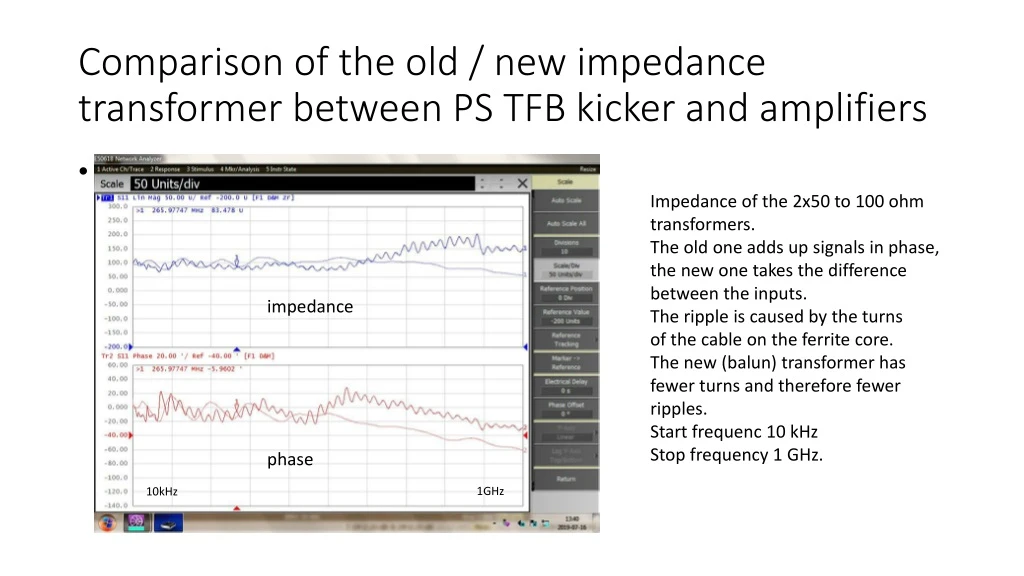
Comparison of the old / new impedance transformer between PS TFB kicker and amplifiers • 1i Impedance of the 2x50 to 100 ohm transformers. The old one adds up signals in phase, the new one takes the difference between the inputs. The ripple is caused by the turns of the cable on the ferrite core. The new (balun) transformer has fewer turns and therefore fewer ripples. Start frequenc 10 kHz Stop frequency 1 GHz. impedance phase 1GHz 10kHz
Circuit diagrams of the transformers. 1 unit with 2 amplifiers 4 x 800W amplifiers combined Each 1500 W On the left : Situation with 2 x 1500 W amplifiers untill 2019 On the right As will be used after LS2 with 2 x 3200W 4 x 800W amplifiers combined
A more detailed description for the summingof the outputs of two amplifiers with a transformer. The transformer TX1 has the right side of the shield connected to the output of a second amplifier that lifts up the potential so that the load sees twice the input voltage. A ferrite core on which the cable is wound prevents a current flowing back to ground through the shield. At the output of the kicker tank there is 50 ohms in series to a cable, connected to an attenuator to provide a test point.
A simplified circuit diagram for the transformer. The transmission line transformer can be represented in a simplified form as a classical transformer with perfect coupling between the windings. Here it shows how the 2 input voltages are simply added. The equivalent resistance shunting the windings together with the coil inductance determines the low frequency -3dB point.
The upper trace shows the input voltage for the kicker tank. The lower traces show the input voltages from the 2 amplifiers. Below 10 kHz the transformer starts to become asymmetrical, this has no consequences because this is below the frequency range that the feedback needs to handle.
Setup after LS2. Kicker tank and balun transformers. Kicker loads outside ring. Each side of the kicker tank is connected to a balun transformer. There will be a total of 8 as the tank has 2 pairs of H and V striplines.
The frequency response of the balun transformer (after LS2) Upper trace output of the balun transformer. Lower traces (overlapping) input of the balun transformer. The inputs have equal amplitude but opposite polarity. There is no assymetry between the inputs.


