Download
1 / 14
140 likes | 324 Views
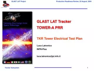
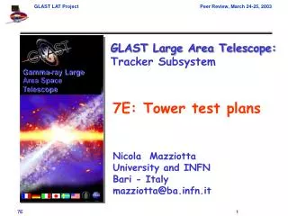
Gamma-ray Large Area Space Telescope. 7E: Tower test plans. GLAST Large Area Telescope: Tracker Subsystem. Nicola Mazziotta University and INFN Bari - Italy mazziotta@ba.infn.it. Outline. Overview Tower vib plan Tower thermal plan Test schedule Summary. Reference LAT Documents:

E N D
Gamma-ray Large Area Space Telescope 7E: Tower test plans GLAST Large Area Telescope:Tracker Subsystem Nicola MazziottaUniversity and INFNBari - Italymazziotta@ba.infn.it
Outline • Overview • Tower vib plan • Tower thermal plan • Test schedule • Summary • Reference LAT Documents: • LAT-MD-00408, LAT Instrument Performance Verification Plan • LAT-SS-00788, LAT Environmental Specification • LAT-TD-01005, Thermal Test Results on Thick Converter Mock-up Trays • LAT-TD-01249, Thermal Test Results for Pre-Engineering Model Trays • LAT-PS-01584, LAT Tracker TraySSD Ladder Panel Assembly Procedure • LAT-TD-00155, Tower Vibration Test Plan • LAT-TD-01840, Tower Thermal Test Plan
Tower vib levels Low frequency sine sweep White Noise High frequency sine sweep
Tower vib set up • Accelerometers set up (TBR): • 3 axial on the shaker table (control accelerometer) • 3 axial on the center of the bottom tray lower surface • 3 axial on the center of the top tray upper surface • 3 axial accelerometer +X sidewall center of the thermal boss tray number 12; • 3 axial accelerometer +Y sidewall near the center of the tray number 10; • 3 axial accelerometer +Y sidewall center of the thermal boss of the tray number 1; • 3 axial accelerometer +Y sidewall center of the thermal boss of the tray number 19; • 3 axial accelerometer -X sidewall center of the thermal boss of the tray number 10; • 3 axial accelerometer -Y sidewall near the center of the tray number 10, on the center plane;
Tower A vib sequence For each axis
B&Flight Towers vib sequence For each axis
Tower A thermal levels 8 Cycles (Tab. 2 LAT-MD-408)
Tower thermal set up Tower covered with a thermal blanket during T-V cycles. The tower has a large number of thermocouples in the read out cables that can be acquired by using the TKR DAQ system. • Additional thermocouples (TBR): • +Y sidewall center of the thermal boss of the tray number 1; • +X sidewall center of the of the tray number 1, on the center plane; • +Y sidewall center of the thermal boss of the tray number 19; • +X sidewall center of the of the tray number 19, on the center plane; • -X sidewall center of the thermal boss of the tray number 10; • -Y sidewall near the center of the tray number 10, on the center plane The temperature control point for the cold part of the cycle will be the coldest thermocouple, while the control point for the hot part of the cycle will be the hottest one.
Summary • Work in progress: • Number of thermal qualification cycles • LPT definition • CPT definition • Use of strain gauges for T-V test ???