Download
1 / 27
270 likes | 406 Views
This document presents a comprehensive summary of noise temperature findings related to cryogenic High Electron Mobility Transistors (HEMTs) as discussed during the ALMA Workshop held on March 21-22, 2011. The analysis covers advancements in NRAO cryogenic amplifiers, the RF signal path, and specifics of the K-Band focal plane array, including receiver characterization, feedhorn arrangements, and thermal gap considerations. Additionally, it outlines system baseline specifications and integration with existing EVLA low-noise amplifier designs, contributing to the ongoing development of radio astronomy technologies.

E N D
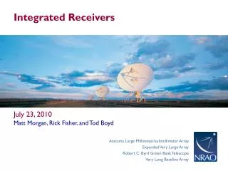
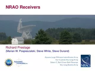
NRAO Receivers • Richard Prestage • (Marian W. Pospieszalski, Steve White, Steve Durand)
Noise Temperature Summary of Cryogenic HEMTs ALMA Workshop, March 21-22, 2011
Mmin Prediction (1991) and State of the Art (2009) NRAO Cryogenic Amplifiers
VLA/EVLATRx versus Frequency TRx = m·F + b ; m = 0.5ºK/ GHz ; b = 8ºK NRAO Cryogenic Amplifiers
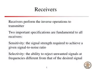
The RF Signal Path The Feedhorn: Compact corrugated horn.
The RF Signal Path A top view of the 15K cold plate and RF signal path: The input to the cryostat. The charcoal trap, the heaters and the thermostat.
The RF Signal Path(cont.) The thermal gap and OMT assemblies: Foam window. Gap set to 5mils. The full assembly forms the circular-to-square transition, the square to quad-ridge taper and the quad-ridge to coaxial sections.
The RF Signal Path(cont.) The RF Tree: Thermal gap/RF choke. Ortho-mode transducer. 90°Quadrature hybrid coupler. Cryo-isolator and calibration coupler. Three stage NRAO Cryo-3 InP HFET low noise amplifier.
K Band Focal Plane Array(Shanghai) Steven D. White*, Matt Morgan, Felix J. Lockman, Eric Bryerton, Glen Langston, Roger Norrod, Bob Simon,Galen Watts, Sivasankaran Srikanth, Gary Anderson
GBT K-Band Array Amplifiers at 19 K Green Bank, West Virginia, January 11, 2009
Feedhorn Arrangement • GBT: • 36” mounting ring on the receiver turret would support about 60 K-Band feedhorns. • 3.45” spacing (~2.5 HPBW) • Shanghai: • Feed Design. • Efficiency ? • Spacing? • Mechanical Impact.
Compact Corrugated Feedhorns 3.4” O.D. Feedhorns 22 GHz Telescope Beams
Thermal Gap • 0.543" circular waveguide • 0.010" gap with choke groove • upper half at 300 K, lower at 15 K • hollow, shaped G10 supports • optimized for weight, strength, and thermal isolation • Cuming Microwave PS-102 foam for vacuum seal • Cuming Eccobond 45 epoxy • 3-mil Kapton vapor seal
Gapped WR42 Sliding Waveguide Output Transition • 0.360” maximum travel • ∆ length on cool-down: ~0.144” • Stable at final temperature • Chomerics 1285 conductive elastomer • Ecco-foam PS102 with 3 mil Kapton
Sliding Waveguide/Thermal Gap Assembly Thermal Gap and 20 cm SS waveguide: 1.7 Watts 1st Stage Load. 30 cm SS coax: 0.54 Watts 1st Stage Load. Total: 1st Stage 18 W; 2nd Stage 3 W. Contraction from 300K to 15K is ~ 4.1 mm of total 6.35 mm.
Downconverter Size Dominated by DC Control Functions PCB Side MMIC Side
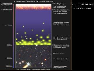
Snakes of Star Formation KFPA NH3 (1,1) contours on Spitzer Glimpse Image The Galaxy is rich in Snakes of star forming clouds: Finn and Jackson, in preparation.
Langston, Batistti, Jones 2011, in preparation Also see posters by Batistti et al and Jones et al
The National Radio Astronomy Observatory is a facility of the National Science Foundationoperated under cooperative agreement by Associated Universities, Inc. www.nrao.edu • science.nrao.edu