Download
1 / 19
190 likes | 356 Views
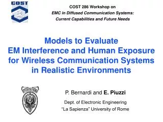
Models to Evaluate EM Interference and Human Exposure for Wireless Communication Systems in Realistic Environments . COST 286 Workshop on EMC in Diffused Communication Systems: Current Capabilities and Future Needs. P. Bernardi and E. Piuzzi Dept. of Electronic Engineering

E N D
Models to EvaluateEM Interference and Human Exposure for Wireless Communication Systems in Realistic Environments COST 286 Workshop onEMC in Diffused Communication Systems:Current Capabilities and Future Needs P. Bernardi and E. Piuzzi Dept. of Electronic Engineering “La Sapienza” University of Rome
Outline • Introduction • Possible EM field sources • Possible EM interference targets • Operating environment • EM interference assessment • External and internal parameters • Numerical modeling: hybrid UTD / FDTD model • Examples in realistic scenarios • Coupling of a microstrip line with the field radiated by a WLAN • Human exposure to a BTS antenna • Conclusions and developments
Possible EM field sources • Base stations (GSM and UMTS systems) • Coverage: 100 m 10 km (macrocellular systems) • Frequency: 900 2000 MHz • Power: 25 mW 20 W • Data rate: 10 kb/s 2 Mb/s • Wireless LANs (IEEE 802.11b, HIPERLAN) • Coverage: single room / building (microcellular systems) • Frequency: 2.4 5.2 GHz • Power: 100 mW • Data rate: 10 Mb/s • Bluetooths • Coverage: 10 m (picocellular systems) • Frequency: 2.4 GHz • Data rate: 300 400 kb/s • Power: 1 mW
Possible EM interference targets • Communication systems operating in the same frequency band • Interfering signal received by the antenna radio link performance degradation loss of communication / data rate reduction • Electronic equipment / Medical devices • Induced currents in a connecting cable disturbance inside the system system malfunction • Induced disturbances inside an electronic apparatus system malfunction / apparatus break • Human beings • Induced power absorption inside the biological tissues temperature elevations / specific effects adverse health effect
Operating environment • BTS are almost entirely installed in outdoor locations, but the radiated field penetrates also inside buildings. • WLANs and Bluetooths mainly operate in indoor environment. • The highest concentration of possible interference targets can be expected in an indoor environment. • Field propagation in indoor environment is dominated by multiple reflection / diffraction processes due to the presence of room walls and furniture.
EM interference assessment (1/2) • EM field levels in the environment (external parameter) must be evaluated • In order to assess if a dangerous interference can occur suitable internal parameters must be estimated • Bit Error Rate (BER) for digital communication systems • Induced disturbances for electronic equipment • Specific Absorption Rate (SAR) for human beings • For practical reasons threshold levels referred to the external EM field are used • Maximum Carrier-to-Interference Ratio (CIR) • Immunity Level (EMC standards) • Reference Level (human exposure guidelines)
EM interference assessment (2/2) • Immunity levels are experimentally tested exposing the electronic equipment to a uniform plane wave. • Reference levels for human exposure have been theoretically derived from threshold whole-body SAR values (with an appropriate safety factor) assuming uniform plane wave exposure of various body models. • In realistic environments exposure fields are far from being uniform plane waves. • A direct evaluation of the relevant internal parameter might be useful in order to establish if a source can: • Cause malfunctions to the considered electronic equipment • Pose any health risk for people
Numerical modeling • The problem requires characterization of • Field propagation in complex scenarios • Field interaction with electronic equipment / human body phantom • UTD model • Efficient modeling of high-frequency field propagation • Not suitable to study interaction between the EM field and dielectric bodies of arbitrary shape • FDTD technique • Efficient modeling of interaction between the field and heterogeneous bodies of arbitrary shape • Huge computational costs for complex scenarios Hybrid UTD / FDTD model
Environment Elements Tx Antenna Equivalence surface d a FDTD Region a) direct ray-path b) GO ray-path c) UTD ray-path d) UTD ray-path c b UTD / FDTD model 2 steps • FDTD evaluation of induced field in the exposed target • UTD computation of exposure field on an equivalence surface
Example 1: WLAN – microstrip coupling f = 2.44 GHz; Pirr = 250 mW; Tx = λ/2 dipole reflector antenna Tx @ (3.5; 0.0; 2.5) Microstrip @ (1.75; 2.5; 1.0) Length = 25 cm Z0 = 50 The shadowed region indicates the field computation area P. Bernardi, R. Cicchetti, O. Testa,27th URSI General Assembly, Aug. 2002
Validation of the UTD heuristic diffraction coefficient • Modeling of field diffraction from penetrable wedges and junctions formed by thin plates • Evaluation of the field inside penetrable objects εr = 3 f = 30 GHz ρ = 2 λ0 —P. Bernardi, R. Cicchetti, O. Testa, IEEE Trans. Antennas and Propagat., Feb. 2002 ◦ ◦ A. J. Booysen, C. W. I. Pistorius, IEEE Trans. Antennas and Propagat., April 1992
Field distribution f = 2.44 GHz Pirr = 250 mW Tx = λ/2 dipole reflector antenna Tx @ (3.5; 0.0; 2.5) GO Field: up to 5 reflected/transmitted contributions UTD Field: up to 3 reflected/transmitted contributions Empty room Furnished room
EMI prediction – Induced current f = 2.44 GHz Pirr = 250 mW Tx = λ/2 dipole reflector antenna Tx @ (3.5; 0.0; 2.5) Microstrip @ (1.75; 2.5; 1.0) Z0 = 50 ; Length = 25 cm A TL model is used to predict induced current on the microstrip line Empty room Furnished room
Example 2: human exposure inside a room in front of a BTS Subject phantom: • “Visible Human” • 3-mm resolution • 31 tissues Antenna parameters: • -3 dB hor. = 64° • -3 dB vert. = 8° • Prad = 30 W • G = 18 dBi P. Bernardi et al., IEEE Trans. Microwave Theory and Tech., Dec. 2003 (to be published)
UTD / FDTD validation rms-field maps on the central yz-sectionof the subject’s domain (GSM900 – f = 947.5 MHz) GO UTD UTD/FDTD
Exposure field distributions Field maps 1 m above the floor in the absence of the subject UMTS (2140 MHz) GSM900 (947.5 MHz)
SAR distributions dB W/kg GSM900 UMTS
Conclusions and developments • A UTD / FDTD model, useful to study EM interference problems in realistic environments, has been developed. • The model has already been applied to study exposure of a subject inside a room illuminated by an outdoor GSM / UMTS base station antenna. • The model will be applied to evaluate disturbance levels inside realistic targets located in a complex indoor environment where a WLAN system operates. • The model can be used to predict possible interferences and / or exposure hazards during the planning stage of indoor wireless communication systems.
GSM 900 UMTS / WLAN Material characteristics