Download
1 / 11
120 likes | 137 Views
Explore the capabilities of the QD0 superconducting solenoid transformer during a collaborative meeting in 2011 at Ma.Ri.S.A., including details on magnetic flux density, inductance, variable temperature cryostat, and more. The secondary winding, mechanical support, current measurement setup, calibration, and quench protection methods are also discussed.

E N D
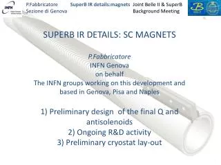
SuperB 2nd Collaboration Meeting Frascati, December 13-16 2011 Test of QD0 Riccardo Musenich INFN-Genova
Superconducting solenoid: • Magnetic flux density (center) 6 T @ 1000 A • Inductance 6.4 H • Internal bore 0.50 m • Heigth 0.62 m • Variable temperature cryostat: • Temperature range 4.2 – 30 K • Free bore 0.42 m
Rj Lp Ls Lc Lp = 6.4 H; Lc = 340 µH; Ls = 90 µH QD0 Secondary Winding (10 turns)
The use of the superconducting transformer allows reaching high current values (in the order of several tens of KA) without huge power supply and current leads. Moreover, as the amount of energy pumped in the sample is limited, it helps protecting the magnet in case of quench.
To maximize the current transformer ratio Ls = 340 µH (20 turns) With 10 turns stored energy: 60% transformer ratio: 85% Ls = Lc Transformer Ratio Lc = 340 µH Ls = 90 µH Lc
10 turns wound with 2 NbTi wires in // H=38 mm = 400 mm QD0 Mechanical support (Al alloy) Secondary winding Hall probe holder Superconducting bus bars
Current measurement: 2 Hall probes symmetrically positioned at 0.12 m from the secondary center Calibration of the Hall probes
Quench protection If a quench is detected by the QDS, two capacitor banks are discharged on two groups of heaters (thin resistors placed on the secondary winding and on the magnet) in order dissipating the stored energy over the entire structure. joint quench heaters QDS secondary winding developing resistance joint