Download
1 / 31
320 likes | 860 Views
FINITE STATE MACHINES - II. STATE MINIMIZATION PARTITIONING MINIMIZATION PROCEDURE VENDING MACHINE EXAMPLE ANALYSIS OF SYNCHRONOUS SEQUENTIAL CIRCUITS PROCEDURE EXAMPLE ALGORITHMIC STATE MACHINES (ASM) CHARTS COMPLETE FSM DESIGN EXAMPLE PARALLEL-TO-SERIAL CONVERTER WITH PARITY GENERATOR.

E N D
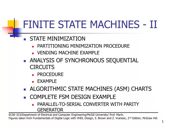
FINITE STATE MACHINES - II • STATE MINIMIZATION • PARTITIONING MINIMIZATION PROCEDURE • VENDING MACHINE EXAMPLE • ANALYSIS OF SYNCHRONOUS SEQUENTIAL CIRCUITS • PROCEDURE • EXAMPLE • ALGORITHMIC STATE MACHINES (ASM) CHARTS • COMPLETE FSM DESIGN EXAMPLE • PARALLEL-TO-SERIAL CONVERTER WITH PARITY GENERATOR __________________________________________________ ECSE-323/Department of Electrical and Computer Engineering/McGill University/ Prof. Marin. Figures taken from Fundamentals of Digital Logic with VHDL Design, S. Brown and Z. Vranesic, 2nd Edition, McGraw Hill.
FINITE STATE MACHINES - II • STATE MINIMIZATION • PARTITIONING MINIMIZATION PROCEDURE • DEFINITION: Two states Si and Sj are said to be equivalent if and only if for every input sequence , the same output sequence will be produced regardless of whether Si or Sj are the initial states. • DEFINITION OF 1-SUCCESSOR : If the machine moves from state Si to state Sv when input w = 1, then we say that Sv is a 1-successor of Si • DEFINITION OF 0-SUCCESSOR : If the machine moves from state Sj to state Su when input w = 0, then we say that Su is a 0-successor of Si IF STATES Si AND Sj ARE EQUIVALENT, THEN THEIR CORRESPONDING K-SUCCESSORS (FOR ALL K) ARE ALSO EQUIVALENT. __________________________________________________ ECSE-323/Department of Electrical and Computer Engineering/McGill University/ Prof. Marin. Figures taken from Fundamentals of Digital Logic with VHDL Design, S. Brown and Z. Vranesic, 2nd Edition, McGraw Hill.
FINITE STATE MACHINES - II • STATE MINIMIZATION • PARTITIONING MINIMIZATION PROCEDURE (CONTINUES) • DEFINITION: A PARTITION CONSISTS OF ONE OR MORE BLOCKS, WHERE EACH BLOCK COMPRISES A SUBSET OF STATES THAT MAY BE EQUIVALENT, BUT THE STATES IN A GIVEN BLOCK ARE DEFINITELY NOT EQUVALENT TO THE STATES IN THE OTHER BLOCK. __________________________________________________ ECSE-323/Department of Electrical and Computer Engineering/McGill University/ Prof. Marin. Figures taken from Fundamentals of Digital Logic with VHDL Design, S. Brown and Z. Vranesic, 2nd Edition, McGraw Hill.
FINITE STATE MACHINES - II • STATE MINIMIZATION • PARTITIONING MINIMIZATION PROCEDURE (CONTINUES) • PROCEDURE: • 1) ALL STATES BELONG TO THE INITIAL PARTITION P1 • 2) P1 IS PARTITIONED IN BLOCKS SUCH THAT THE STATES IN EACH BLOCK GENERATE THE SAME OUTPUT. • 3) CONTINUE TO PERFORM NEW PARTITIONS BY TESTING WHETHER THE K-SUCCESSORS OF THE STATES IN EACH BLOCK ARE CONTAINED IN ONE BLOCK. THOSE STATES WHOSE K-SUCCESSORS ARE IN DIFFERENT BLOCKS CANNOT BE IN ONE BLOCK. • 4) PRCEDURE ENDS WHEN A NEW PARTITION IS THE SAME AS .THE PREVIOUS PARTITION
Next state Present Output z state w = 0 w = 1 A B C 1 B D F 1 C F E 0 D B G 1 E F C 0 F E D 0 G F G 0 FINITE STATE MACHINES - II • STATE MINIMIZATION • PARTITIONING MINIMIZATION PROCEDURE (CONTINUES) • EXAMPLE: Consider the following state transition table P1 = (ABCDEFG) P2 = (ABD)(CEFG) Diff. Outputs. Because (CEFG) 0-successors are (FFEF) in same block, (CEFG) 1-successors are (ECDG) in diff. block, F must be different from C, E and G P3 = (ABD)(CEG)(F) P4 = (AD)(B)(CEG)(F) Same process for (AD) and (CEG) gives P5 = (AD)(B)(CEG)(F) P5 = P4
Next state Present Output Nextstate Present Output z state w = 0 w = 1 z state w = 0 w = 1 A B C 1 A B C 1 B D F 1 B A F 1 C F E 0 C F C 0 D B G 1 F C A 0 E F C 0 F E D 0 G F G 0 FINITE STATE MACHINES - II • STATE MINIMIZATION • PARTITIONING MINIMIZATION PROCEDURE (CONTINUES) • EXAMPLE (CONTINUES): MINIMAL STATE TRAMSITION TABLE ORIGINAL TABLE P4 = (AD)(B)(CEG)(F) MINIMIZED TABLE
FINITE STATE MACHINES - II • STATE MINIMIZATION • VENDING MACHINE EXAMPLE Design an FSM that will dispense candy under the following conditions: • 1.- The machine accepts nickels and dimes • 2.- 15 cents releases a candy from the machine • 3.- If 20 cents is deposited, the machine will not return the change, but it credit the buyer with 5 cents and wait for the buyer to make a second purchase __________________________________________________ ECSE-323/Department of Electrical and Computer Engineering/McGill University/ Prof. Marin. Figures taken from Fundamentals of Digital Logic with VHDL Design, S. Brown and Z. Vranesic, 2nd Edition, McGraw Hill.
Clock sense N sense D N D (a) Timing diagram FINITE STATE MACHINES - II • STATE MINIMIZATION • VENDING MACHINE EXAMPLE (Continues) __________________________________________________ ECSE-323/Department of Electrical and Computer Engineering/McGill University/ Prof. Marin. Figures taken from Fundamentals of Digital Logic with VHDL Design, S. Brown and Z. Vranesic, 2nd Edition, McGraw Hill.
N sense Q Q D D N Clock Q Q N (b) Circuit that generates FINITE STATE MACHINES - II • STATE MINIMIZATION • VENDING MACHINE EXAMPLE (Continues) __________________________________________________ ECSE-323/Department of Electrical and Computer Engineering/McGill University/ Prof. Marin. Figures taken from Fundamentals of Digital Logic with VHDL Design, S. Brown and Z. Vranesic, 2nd Edition, McGraw Hill.
DN Reset DN ¤ S1 0 DN DN DN DN D N D ¤ ¤ S2 0 S3 0 ¤ ¤ S4 1 S7 1 N D N DN ¤ S6 0 ¤ S5 1 DN DN N D ¤ ¤ S8 1 S9 1 FINITE STATE MACHINES - II STATE MINIMIZATION: VENDING MACHINE EXAMPLE (Continues) __________________________________________________ ECSE-323/Department of Electrical and Computer Engineering/McGill University/ Prof. Marin. Figures taken from Fundamentals of Digital Logic with VHDL Design, S. Brown and Z. Vranesic, 2nd Edition, McGraw Hill.
Next state Present Output state z DN =00 01 10 11 – S1 S1 S3 S2 0 – S2 S2 S4 S5 0 – S3 S3 S6 S7 0 – – – S4 S1 1 – – – S5 S3 1 – S6 S6 S8 S9 0 – – – S7 S1 1 – – – S8 S1 1 – – – S9 S3 1 FINITE STATE MACHINES - II • STATE MINIMIZATION • VENDING MACHINE EXAMPLE (Continues) P1 = (S1, S2, S3, S4, S5, S6, S7, S8, S9) P2 = (S1, S2, S3, S6)(S4, S5, S7, S8, S9) P3 = (S1)(S3)(S2, S6)(S4, S5, S7, S8, S9) P4 = (S1)(S3)(S2, S6)(S4, S7, S8)(S5,S9) P5 = (S1)(S3)(S2, S6)(S4, S7, S8)(S5,S9) __________________________________________________ ECSE-323/Department of Electrical and Computer Engineering/McGill University/ Prof. Marin. Figures taken from Fundamentals of Digital Logic with VHDL Design, S. Brown and Z. Vranesic, 2nd Edition, McGraw Hill.
DN ¤ S1 0 Next state Present Output state z N DN =00 01 10 11 DN – S1 S1 S3 S2 0 ¤ S3 0 – D S2 S2 S4 S5 0 – S3 S3 S2 S4 0 DN DN N – – – S4 S1 1 – – – S5 S3 1 D ¤ ¤ S2 0 S5 1 DN N D ¤ S4 1 FINITE STATE MACHINES - II STATE MINIMIZATION: VENDING MACHINE EXAMPLE (Continues) MINIMIZED STATE TRANSITION TABLE AND DIAGRAM
DN ¤ DN 0 ¤ S1 0 S1 N ¤ ¤ N 0 D 1 DN ¤ DN 0 ¤ S3 0 D S3 ¤ ¤ N 1 D 0 DN DN N D ¤ ¤ N 0 D 1 ¤ ¤ S2 0 S5 1 DN N S2 D ¤ S4 1 ¤ DN 0 FINITE STATE MACHINES - II STATE MINIMIZATION: VENDING MACHINE EXAMPLE (Continues) MINIMIZED STATE TRANSITION DIAGRAM: Moore-type versus Mealy-type MOORE-TYPE MEALY_TYPE
FINITE STATE MACHINES - II • ANALYSIS OF SYNCHRONOUS SEQUENTIAL CIRCUITS • PROCEDURE: is the reverse of the synthesis process. • 1.-OUTPUTS OF FLIP-FLOPS ARE THE INTERNAL STATES. • 2.- INPUT EQUATIONS TO FLIP-FLOPS DETERMINE NEXT INTERNAL STATE. • 3.- EXCITATION TABLE IS CONSTRUCTED FROM THESE INPUT EQUATIONS TO FLIP-FLOPS. OUTPUT EQUATIONS ARE PRODUCED. • 4.- THE STATE-ASSIGNED TABLE IS PRODUCED FROM THE EXCITATION TABLE • 5.- THE STATE-TRANSITION TABLE IS PRODUCED BY ASSIGNING A STATE IDENTIFICATION LETTER TO EACH ASSIGNED STATE. • 6.- THE STATE-TRANSITION DIAGRAM IS PRODUCED FROM THE STATE- TRANSITION TABLE. __________________________________________________ ECSE-323/Department of Electrical and Computer Engineering/McGill University/ Prof. Marin. Figures taken from Fundamentals of Digital Logic with VHDL Design, S. Brown and Z. Vranesic, 2nd Edition, McGraw Hill.
FINITE STATE MACHINES - II • ANALYSIS OF SYNCHRONOUS SEQUENTIAL CIRCUITS • EXAMPLE: ANALYZE THE FOLLOWING CIRCUIT Exitation equations: DY1 = w !y1 + w y2 DY2 = w y1 + w y2 z = y1 y2 Next state equations: Y1 = DY1 = w !y1 + w y2 Y2 = DY2 = w y1 + w y2 __________________________________________________ ECSE-323/Department of Electrical and Computer Engineering/McGill University/ Prof. Marin. Figures taken from Fundamentals of Digital Logic with VHDL Design, S. Brown and Z. Vranesic, 2nd Edition, McGraw Hill.
Next State Present Output state w = 0 w = 1 z y y 2 1 Y Y Y Y 2 1 2 1 0 0 0 0 01 0 0 1 0 0 10 0 1 0 0 0 11 0 1 1 0 0 11 1 (a) State-assigned table FINITE STATE MACHINES - II • ANALYSIS OF SYNCHRONOUS SEQUENTIAL CIRCUITS EXAMPLE (Continues) Exitation equations: DY1 = w !y1 + wy2 DY2= w y1 + w y2 z = y1 y2 Next state equations: Y1 = DY1 = w !y1 + w y2 Y2 = DY2 = w y1 + w y2 __________________________________________________ ECSE-323/Department of Electrical and Computer Engineering/McGill University/ Prof. Marin. Figures taken from Fundamentals of Digital Logic with VHDL Design, S. Brown and Z. Vranesic, 2nd Edition, McGraw Hill.
Next State Present Output Next state state w = 0 w = 1 Present Output z y y state z 2 1 Y Y Y Y w = 0 w = 1 2 1 2 1 0 0 0 0 01 0 A A B 0 0 1 0 0 10 0 B A C 0 1 0 0 0 11 0 C A D 0 1 1 0 0 11 1 D A D 1 (a) State-assigned table (b) State table FINITE STATE MACHINES - II • ANALYSIS OF SYNCHRONOUS SEQUENTIAL CIRCUITS EXAMPLE (Continues) __________________________________________________ ECSE-323/Department of Electrical and Computer Engineering/McGill University/ Prof. Marin. Figures taken from Fundamentals of Digital Logic with VHDL Design, S. Brown and Z. Vranesic, 2nd Edition, McGraw Hill.
y J 1 1 w Q J z K Q K 1 y J 2 2 Q J Clock K Q K 2 Resetn FINITE STATE MACHINES - II • ANALYSIS OF SYNCHRONOUS SEQUENTIAL CIRCUITS ANOTHER EXAMPLE: Analyze the following circuit __________________________________________________ ECSE-323/Department of Electrical and Computer Engineering/McGill University/ Prof. Marin. Figures taken from Fundamentals of Digital Logic with VHDL Design, S. Brown and Z. Vranesic, 2nd Edition, McGraw Hill.
y J 1 1 w Q J z K Q K 1 y J 2 2 Q J Clock K Q K 2 Resetn FINITE STATE MACHINES - II • ANALYSIS OF SYNCHRONOUS SEQUENTIAL CIRCUITS ANOTHER EXAMPLE (Continues) Excitation Equations J1 = w K1 = !w + !y2 J2 = w y1 K2 = !w z = y1 y2 __________________________________________________ ECSE-323/Department of Electrical and Computer Engineering/McGill University/ Prof. Marin. Figures taken from Fundamentals of Digital Logic with VHDL Design, S. Brown and Z. Vranesic, 2nd Edition, McGraw Hill.
Flip-flop inputs Present Output state w = 0 w = 1 y y z 2 1 J K J K J K J K 2 2 1 1 2 2 1 1 00 01 0 1 0 0 1 1 0 01 01 0 1 1 0 1 1 0 10 01 0 1 0 0 1 0 0 11 01 0 1 1 0 1 0 1 FINITE STATE MACHINES - II • ANALYSIS OF SYNCHRONOUS SEQUENTIAL CIRCUITS ANOTHER EXAMPLE (Continues) Excitation Equations J1 = w K1 = !w + !y2 J2 = w y1 K2 = !w z = y1 y2 __________________________________________________ ECSE-323/Department of Electrical and Computer Engineering/McGill University/ Prof. Marin. Figures taken from Fundamentals of Digital Logic with VHDL Design, S. Brown and Z. Vranesic, 2nd Edition, McGraw Hill.
Flip-flop inputs Next State Present Present Output Output state w = 0 w = 1 state w = 0 w = 1 z y y y y z 2 1 Y Y Y Y 2 1 2 1 2 1 J K J K J K J K 2 2 1 1 2 2 1 1 0 0 0 0 01 0 00 01 0 1 0 0 1 1 0 0 1 0 0 10 0 01 01 0 1 1 0 1 1 0 1 0 0 0 11 0 10 01 0 1 0 0 1 0 0 1 1 0 0 11 1 11 01 0 1 1 0 1 0 1 FINITE STATE MACHINES - II • ANALYSIS OF SYNCHRONOUS SEQUENTIAL CIRCUITS ANOTHER EXAMPLE (Continues) EXCITATION TABLE STATE-ASSIGNED TABLE __________________________________________________ ECSE-323/Department of Electrical and Computer Engineering/McGill University/ Prof. Marin. Figures taken from Fundamentals of Digital Logic with VHDL Design, S. Brown and Z. Vranesic, 2nd Edition, McGraw Hill.
Next State Present Output Next state state w = 0 w = 1 Present Output z y y state z 2 1 Y Y Y Y w = 0 w = 1 2 1 2 1 0 0 0 0 01 0 A A B 0 0 1 0 0 10 0 B A C 0 1 0 0 0 11 0 C A D 0 1 1 0 0 11 1 D A D 1 (a) State-assigned table (b) State table FINITE STATE MACHINES - II • ANALYSIS OF SYNCHRONOUS SEQUENTIAL CIRCUITS EXAMPLE (Continues) __________________________________________________ ECSE-323/Department of Electrical and Computer Engineering/McGill University/ Prof. Marin. Figures taken from Fundamentals of Digital Logic with VHDL Design, S. Brown and Z. Vranesic, 2nd Edition, McGraw Hill.
State name Output signals 0 (False) 1 (True) Condition or actions expression (Moore type) (a) State box (b) Decision box Conditional outputs or actions (Mealy type) (c) Conditional output box FINITE STATE MACHINES - II • ALGORITHMIC STATE MACHINES (ASM) CHARTS • DEFINITION: An ASM is a type of flowchart that can be used to represent the state transitions and generated outputs for LARGE FSMs. • THREE TYPES OF ELEMENTS: • STATE BOX, DECISION BOX, CONDITIONAL OUTPUT BOX. __________________________________________________ ECSE-323/Department of Electrical and Computer Engineering/McGill University/ Prof. Marin. Figures taken from Fundamentals of Digital Logic with VHDL Design, S. Brown and Z. Vranesic, 2nd Edition, McGraw Hill.
Reset Reset A w = 1 ¤ ¤ w = 0 A z = 0 B z = 0 0 w = 0 w 1 w = 1 w = 0 B ¤ C z = 1 0 w w = 1 1 C z 0 1 w FINITE STATE MACHINES - II • ALGORITHMIC STATE MACHINES (ASM) CHARTS (Continues) • Example: Moore-type __________________________________________________ ECSE-323/Department of Electrical and Computer Engineering/McGill University/ Prof. Marin. Figures taken from Fundamentals of Digital Logic with VHDL Design, S. Brown and Z. Vranesic, 2nd Edition, McGraw Hill.
Reset ¤ w = 1 z = 0 ¤ ¤ w = 0 z = 0 w = 1 z = 1 B A ¤ w = 0 z = 0 FINITE STATE MACHINES - II • ALGORITHMIC STATE MACHINES (ASM) CHARTS (Continues) • EXAMPLE (Mealy-type) __________________________________________________ ECSE-323/Department of Electrical and Computer Engineering/McGill University/ Prof. Marin. Figures taken from Fundamentals of Digital Logic with VHDL Design, S. Brown and Z. Vranesic, 2nd Edition, McGraw Hill.
Reset r r r 1 2 3 Reset Idle Idle r r 1 1 1 r 1 ¤ gnt1 g = 1 1 gnt1 1 0 0 r r g 1 r r r 1 1 2 1 2 1 r 2 ¤ gnt2 g = 1 2 1 0 gnt2 0 r r g 2 r 2 r r r 2 3 1 2 3 0 1 r 3 ¤ gnt3 g = 1 3 1 gnt3 0 r g 3 r 3 3 FINITE STATE MACHINES - II ALGORITHMIC STATE MACHINES (ASM) CHARTS (Continues) ANOTHER EXAMPLE (ARBITER MOORE-TYPE FSM): FSM THAT CONTROLS THE ACCESS BY VARIOUS DEVICES TO A SHARED RESOURCE IN A GIVEN SYSTEM. ONLY ONE DEVICE CAN USE THE RESOURCE AT A TIME.
FINITE STATE MACHINES - II • COMPLETE FSM DESIGN EXAMPLE PARALLEL-TO-SERIAL CONVERTER WITH PARITY GENERATOR • Word description • Design a digital systems that will convert an 8-bit parallel message, (b7 , b6 , b5 , b4 , b3 , b2 , b1 , b0), composed of 7-bit ASCII character plus an initially set to 0 parity bit, into an 8-bit serial message with the correct parity bit set into bit b7 . __________________________________________________ ECSE-323/Department of Electrical and Computer Engineering/McGill University/ Prof. Marin. Figures taken from Fundamentals of Digital Logic with VHDL Design, S. Brown and Z. Vranesic, 2nd Edition, McGraw Hill.
FINITE STATE MACHINES - II • COMPLETE FSM DESIGN EXAMPLE PARALLEL-TO-SERIAL CONVERTER WITH PARITY GENERATOR • BLOCK DIAGRAM (Data Path and Control Unit) __________________________________________________ ECSE-323/Department of Electrical and Computer Engineering/McGill University/ Prof. Marin. Figures taken from Fundamentals of Digital Logic with VHDL Design, S. Brown and Z. Vranesic, 2nd Edition, McGraw Hill.
FINITE STATE MACHINES - II • COMPLETE FSM DESIGN EXAMPLE PARALLEL-TO-SERIAL CONVERTER WITH PARITY GENERATOR • STATE TRANSITION TABLE __________________________________________________ ECSE-323/Department of Electrical and Computer Engineering/McGill University/ Prof. Marin. Figures taken from Fundamentals of Digital Logic with VHDL Design, S. Brown and Z. Vranesic, 2nd Edition, McGraw Hill.
FINITE STATE MACHINES - II • COMPLETE FSM DESIGN EXAMPLE PARALLEL-TO-SERIAL CONVERTER WITH PARITY GENERATOR • STATE-ASSIGNED TABLE • CHOICE OF FLIP-FLOPS AND EXCITATION EQUATION Dy = Y = w y __________________________________________________ ECSE-323/Department of Electrical and Computer Engineering/McGill University/ Prof. Marin. Figures taken from Fundamentals of Digital Logic with VHDL Design, S. Brown and Z. Vranesic, 2nd Edition, McGraw Hill.
FINITE STATE MACHINES - II • COMPLETE FSM DESIGN EXAMPLE PARALLEL-TO-SERIAL CONVERTER WITH PARITY GENERATOR • CIRCUIT __________________________________________________ ECSE-323/Department of Electrical and Computer Engineering/McGill University/ Prof. Marin. Figures taken from Fundamentals of Digital Logic with VHDL Design, S. Brown and Z. Vranesic, 2nd Edition, McGraw Hill.