Download
1 / 17
200 likes | 337 Views
This comprehensive guide explores the principles and technology behind electroluminescence (EL) in display systems. It covers fundamental concepts of EL, including electron-hole pair recombination, high-field EL, and various display technologies like LEDs and OLEDs. The document discusses color production approaches, layer structures, and technological advancements in EL, including Active Matrix Electroluminescent (AMEL) displays. It further examines applications in cars, HUDs, and camcorders, along with a comparative analysis of EL features, advantages, and limitations.

E N D
Electroluminescence Displays Fakultät für Elektrotechnik und Informationstechnik Lehrstuhl für Kommunikationstechnik Prof. Dr.-Ing. Rüdiger Kays Jens Bömer jcbsystems@gmx.de
Electroluminescence: Basics & Technology • Introduction • Principles of Electroluminescence (EL) • general effect • high-field EL • Technological Realization • layer structure • Selected Approaches to • produce colours • make a display • Applications/ Products • Pros & Cons Table of Contents
Motivating Forces • tendency to miniaturizement • fast response for video services • low power consumption Introduction
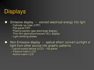
Electroluminescence High Field EL LED & OLED non-thermal conversionof electrical energy into light • pn-junction • electron-hole pair recombination • phosphorus material • hot-electrons • impact excitation Introduction
E2 Luminescence E E1 Fluorescencet 1s Phosphorescencet 1min - ... Eg E0 • Requirements • band gap (Eg) higher than 3.0eV • special semiconductor • insulator • electrical energy is converted into light energy • operation at low temperatures possible Principles of EL
Electron transport Al • insulator/ phosphor interface states • electrons tunnel into phosphor • electrons accelerated by electric field (high energy or “hot” electrons > 2 eV) e- ... topinsulator excited state ITO bottominsulator Excitation • collisions with lattice/ ímpurity atoms (e.g. Mn) • luminescent impurity absorbs electron‘s energy • excited impurity relaxes by emitting a photon impurityground state High Field EL Principles of EL
electrode AC phosphor ( 600nm) insulator( 250nm) T • insulator/phosphor/insulator stack • insulators limit short current • electric field strength > 1.5 MV/cm • 165 V alternating voltage • thin film EL (TFEL) • wide viewing angle • luminosity controlled by pulse width modulation Technological Realization
Red • ZnS:Mn • organic red filter Green • ZnS:TbOF • SrS:Ce Blue • SrS:Ce • SrS:Cu,Ag Amber • ZnS:Mn rare earth oxidsand oxysulfats(as in CRT) White • stacked layers • SrS:Ce and ZnS:Mn Colourful Materials
Luminance (max.) • red: 70 cd/m2 • green 160 cd/m2 • blue: 100 cd/m2 • white: 470 cd/m2 Efficiency • red: 0.8 lm/W • green: 1.0 lm/W • blue: 0.2 lm/W operating temperature-30° C to 65°C Facts Concerning Colours
LCD: thin film EL Contrast ratio Luminance Viewing angle Power consumption 18:1-150:1 200 cd/m2 100°(recently up to 170°) 20W 150:1 150 cd/m2 > 160° 3W Comparison of EL and LCD
One approach: “Colour by White“ • broad band “white“ phosphor • patterned colour filter • indium-tin oxide (ITO) top electrode • pixel size of 12 or 24 micron simple device fabrication low-cost production Selected Approach to Produce Colors
high integration level • low capacity • less current • reduction of control wires fast response Active Matrix (AMEL)Display Organization EL pixel ITO data line Technological advantages column drivers line drivers Selected Approach to Make a Display
b t • Silicon On Insulator (SOI): • Required isolation between high voltage AC of EL deviceand low voltage digital signals which address each pixel. Technological features Advantages of AMEL • aging characteristics of the phosphor • inverted structure • brightness controlled by pulse width modulation • high resolution (2000 lpi) • reduced power consumption • higher brightness • expanded grayscal capability Selected Approach to Make a Display
instrument panels head-up displays (HUD) What is ACTFEL? ACTFEL: alternating current thin film electroluminescence • transparent • minimize driver‘s eye movement • visibility under sunlight • pixel luminance: • amber: 1200 cd/m2 • green: 500 cd/m2 • used in cars • high reliability • wide temperature range • luminance: • red: 23 cd/m2 • amber: 140 cd/m2 • green: 25 cd/m2 Applications
Products EL foil EL display camcorder car control panel(ACTFEL) head mounteddisplay Products
PRO CONTRA • high resolution • fast response • low power consumption • wide viewing angle • ruggedness • low-cost production • use at low temperatures • visibility under sunlight • inadequate brightness and chromaticity • aging characteristics • high voltage • alternating current Pros and Cons
HFEL bases on high energy electrons (hot electrons) • Self-emitting technology instead of light through (LCD) • Realization with an insulator/phosphor/insulator stack • Multi-colour displays by “white phosphor“ and colour filters • Various monochrome control panels by variation of dopants • Active matrix integration (AMEL) • Application in cars, laptops, head-mounted-displays, camcorder Summary