Download
1 / 18
180 likes | 297 Views
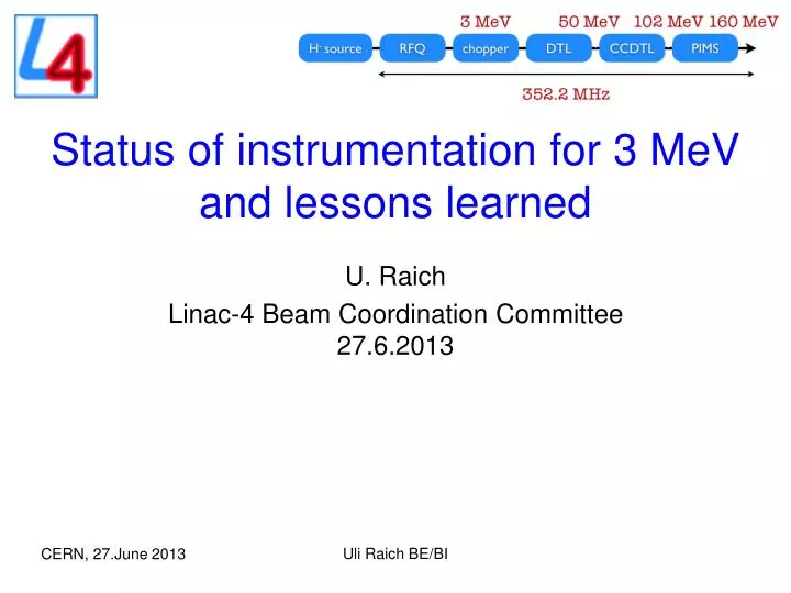
Status of instrumentation for 3 MeV and lessons learned. U. Raich Linac-4 Beam Coordination Committee 27.6.2013. Measurement Line: Emittance meter Spectrometer Transformers Beam Position Monitors Bunch Shape Monitor Halo Monitor Chopper line: Wire Scanners. The 3 MeV measurement line.

E N D
Status of instrumentation for 3 MeV and lessons learned U. Raich Linac-4 Beam Coordination Committee 27.6.2013 UliRaich BE/BI
Measurement Line: • Emittance meter • Spectrometer • Transformers • Beam Position Monitors • Bunch Shape Monitor • Halo Monitor • Chopper line: • Wire Scanners The 3 MeV measurement line Uli Raich BE/BI
Transformers • First instrument used to see the 3 MeV beam • Most advanced of all instruments To be improved: • FPGA code in TRIC card to allow independent definition of integration windows for measurement interval and offset calculation • Better shielding against field of neighboring Quadrupoles • Control relative intensity values along the beam line • Finalize watchdog Uli Raich BE/BI
Transformer signal Uli Raich BE/BI
Chopper rise and fall time Uli Raich BE/BI
Emittance Meter The emittance meter consists of a slit at the beginning of the measurement line and a SEMGrid at its end • Emittance measurement now works (more or less) reliably • Re-do position calibration and get values for beam pipe center • Add electronics to read out all 48 wires (currently only 32) • Adapt evaluation program and calculate emittance and Twiss parameters • Check again ADC offset is the same on all channels • Add steering to center the beam on the SEMGrid • Make sure the beam is not too divergent to loose in the transfer line to the SEMGrid Uli Raich BE/BI
Emittance Plot Uli Raich BE/BI
Profile measurement Profile measurements can be done • On SEMGrid without slit • Using projection from emittance plot • Using slit and transformer • Using slit as scraper + transformer Improvements: • Profile measurements using the transformer have been made semi-manually. This method was not envisaged initially. Should be automated. Uli Raich BE/BI
Profile Measurement with scraping Uli Raich BE/BI
Wire Scanners on Chopper line • In general works not too bad • Profile shapes when creating a waste on the WS are not yet understood • We see a second bump. Is it real? Improvements: • Try an L-shaped wire scanner instead of XThis may decrease possible crosstalk • Make sure to have a very small electronics offset Uli Raich BE/BI
Typical wires scanner profiles Uli Raich BE/BI
Wire heating? 250 µs beam pulse 150 µs beam pulse Uli Raich BE/BI
BPMs BPMs are designed to measure • Beam position • Beam intensity • Beam energy by time of flight between 2 BPMs BPMs are least advanced and need more commissioning time • Beam intensity: The signal shape is exactly the same we see on the BCTs but cross calibration is needed to each BPM (different debunching) • Beam position not ok yet. See losses on the electrodes of the 3rd BPMNeed a straight line without magnetic elements between the 3 BPMs to checkWhen using the slit as 4th position the noise in the position measurement increases due to low intensity • TOF measurement starts working but is not stable yet (timing problem?) Uli Raich BE/BI
Spectrometer • The spectrometer was used to determine the buncher phases and amplitudes • Energy spread measurements have not been done yet(for once this not an instrumentation but more an optics problem) • When inserting the slit, the intensity seen on the SEMGrid is very low • Currently uses old electronics with only 40 channels. To be replaced by new electronics reading all 48 channels Uli Raich BE/BI
Bunch Shape Monitor • The monitor has been tested in beam with the Russian INR team • The buncher settings (phase and amplitude) have been verified against the values obtained with the spectrometer • Device works fine and is easy to use • Before the measurement campaign we had a problem with the NI controller card which has been replaced.The original controller module must be re-installed and the LabView software checked. • Integration into the control system to be prepared Uli Raich BE/BI
Bunch shape in bunching and debunching phase Uli Raich BE/BI
Halo Monitor • The device has been used for less than 1 day • Some beam spots have been measured • Precise timing synchronous with the chopper is still missing Uli Raich BE/BI
Halo Monitor results Uli Raich BE/BI


![Status of Ubiquitous Computing [Lessons Learned So Far]](https://cdn3.slideserve.com/5977007/status-of-ubiquitous-computing-lessons-learned-so-far-dt.jpg)