Download

1 / 35
400 likes | 730 Views
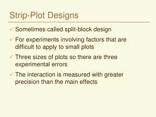
Design Example - Drag Strip “Christmas Tree ”.

E N D
Design Example - Drag Strip “Christmas Tree” A simplified starting timer is to be constructed for a drag strip. To enable the start timing for a race both cars must actuate sensor switches at the start line that indicate they are in position. When the cars are in position, the race judge receives a green light on his control panel and a green light comes on of the “Christmas Tree”. He then presses a race initial button on his control panel. The Christmas tree times through the sequence shown at left. G ready Y 3 sec Y 3 sec Y 3 sec G lane 1 lane 2 et438b-8.pptx
Design Example - Drag Strip “Christmas Tree” When the lower pair of green lamps come on the racers begin. A pair of photo eyes located at the finish line indicate the winner by lighting a blue light for a winner and a amber light for a loser. after the race results are indicated, the judge can press a reset button to prepare the system for the next race Bu lane 1 lane 2 finish sensors A start sensors lane 1 car 1 lane 2 car 2 finish indicators et438b-8.pptx
Design Example - Drag Strip “Christmas Tree” Design Problem 1.) Identify the states, conditions and actions for this system 2.) Construct a flow chart of the logic for this system 3.) Construct a state transition diagram for this system 4.) Design a ladder logic system to implement these functions Part 1: States, Conditions, Actions States S0 : reset S1: cars at start line S2: 1st set red lamps on S3: 2nd set red lamps on S4: 3rd set red lamps on S5: Green lamps on (race start) S6: Lane 1 Wins S7: Lane 2 Wins et438b-8.pptx
Design Example - Drag Strip “Christmas Tree” Define conditions (Inputs) ConditionsI0: reset pressed I1: racer 1 positioned I2: racer 2 positioned I3: race timing initiated I4: 1st set red lamps timed out I5: 2nd set red lamps timed out I6: 3rd set red lamps timed out I7: lane 1 finish photo eye tripped I8: lane 2 finish photo eye tripped I9: start pressed et438b-8.pptx
Design Example - Drag Strip “Christmas Tree” Define actions (Outputs) Actions O0: light green ready lamp O1: light red lamps set 1 O2: light red lamp set 2 O3: light red lamp set 3 O4: light green lamp set O5: light blue lamp 1 if lane 1 wins O6: light blue lamp 2 if lane 2 wins O7: light amber lamp 1 if lane 1 loses O8: light amber lamp 2 if lane 2 loses et438b-8.pptx
Part 2 Flow chart Race initiate pressed 1 Red set 1 on 3 sec Red set 2 on 3 sec Red set 3 on 3 sec Green lamps on Reset 2 sequence X-mas tree lights no Car 1 positioned Yes race in progress no Car 2 positioned no no lane 1 sensor trip lane 2 sensor trip Yes Yes light judge ready lamp Yes light tree ready lamp Bu lane 2 on A lane 1 on lane 1 winner lane 2 loser lane 2 winner lane 1 loser 1 2 et438b-8.pptx
Example State Transition Diagram Start pressed Cars 1 & 2 positioned Ready Red set 1 on S1 S2 Timing initiated S0 Set 1 time-out O0 light ready lamps O1 light Lamps O0 not Red set 2 on Reset S3 Reset pressed O2 light lamps O5, O8 Light correct lamps Reset pressed Set 2 time-out O3 light lamps Lane 1 wins S6 3rd red set on S4 Race start S7 S5 Lane 2 wins O6, O7 Light correct lamps O4 light green lamps et438b-8.pptx
Construct State Equations Start pressed State 0 S1 S0 DeMorgans S6 0 Expand and Simplify S7 Factor Regroup et438b-8.pptx
Construct State Equations State 0 continued Factor Simplify & Regroup 1 Reduced Equation et438b-8.pptx
Construct Ladder Logic et438b-8.pptx
Construct State Equations State 1 S1 S0 et438b-8.pptx
Construct Ladder Logic State 1 Output Equation et438b-8.pptx
Construct State Equations State 2 Set 1 time-out TON#(c,t)=On-delay timer # c = input condition t = time delay S2 so O1 light Lamps O0 not S3 Set 1 time-out State 2 Output Equation S3 State 3 O2 light lamps Set 2 time-out S4 State 3 Output Equation et438b-8.pptx
Construct State Equations State 4 O3 light lamps S4 State 4 Output Equation S5 State 5 S6 S5 O4 light green lamps S7 et438b-8.pptx
Construct State Equations State 5 simplification State 5 Output Equation Block Lane 2 Reset pressed State 6 O5, O8 Light correct lamps S0 State 6 Output Equations S6 et438b-8.pptx
Construct State Equations State 7 Reset pressed S0 Block Lane 1 S7 O6, O7 Light correct lamps Lane 2 wins State 7 Output Equations et438b-8.pptx
Construct Ladder Logic State 6 et438b-8.pptx
Construct Ladder Logic State 7 et438b-8.pptx
Complete System et438b-8.pptx
Complete System et438b-8.pptx
Design Considerations Personnel and Equipment Safety Fail-safe operation - component fail results in little or no damage or inconvenience Common Practice 1.) start sequence by closing NO contacts 2.) stop a sequence by opening NC contact Practice Results:if device fails to start process stops, If started would stop Example: Motor starter et438b-8.pptx
Troubleshooting Tips Common causes of Failure 1.) Dirty or oxidized contacts 2.) Broken wire or loose connection 3.) Up stream power source interrupted causing input device to de-activate Other Issues Contact operation sequence break-before-make standard See previous example limit switches et438b-8.pptx
Programmable Logic Controllers (PLC) Microprocessor-based controller that implements ladder logic through software and hardware interface. Definition of PLC Digital apparatus using programmable memory and stored programs for implementing Logic Timing Sequencing Counting Basic Block Diagram of A PLC Field devices Field devices (sensors) INPUT MODULES OUTPUT MODULE CPU (control values, solenoids) USER Memory Programmer et438b-8.pptx
PLC Operation in Run Mode 1. Scan all Inputs Detect change in status of field devices (Limit switches Pressure switches, etc.) 2. Execute control program based on user logic design 3. Test output status against program values. 4. Update output to fit changes dictated by input change Time from 1 to 4 called scan time. Can be important in programs et438b-8.pptx
Typical PLC Input/Output Modules PLC I/O designed to connect to industrial devices I/O grouped on cards with 8, 16, 24,32 inputs Dry contacts (standard switches) motor contactors Pressure, temperature, limit, flow switches 1 set terminals (com, n) = 1 I/O point Solid state sensors (electronic) proximity switches, photo eyes etc. Voltage levels24 - 240 Vac 24-240 Vdc TTL levels, Sourcing and sinking I/O et438b-8.pptx
PLC I/O Interfacing PLC’s use memory mapped I/O PLC uses microprocessors with 8-16 bit words. Each I/O point identified by location in memory. Terminals have unique addresses represented by decimal, octal or binary number. (commonly decimal) Each memory word maps to group of I/O points Bits represent status of I/O field devices 1=on, 0=off et438b-8.pptx
PLC I/O Interfacing Level 3: I/O point. Type of point and terminal number For expandable PLCs Level 2: Slot identifier (type of I/O card) Level 1: Rack or chassis identifier Non-expandable PLCs use fixed addressing: All slot 0 et438b-8.pptx
PLC I/O Interfacing Addressing of I/O cards (Allen-Bradley (A-B)) A-B uses decimal expandable addressing for most PLCs Slot Number X:n Function I/O Addressing Specific I/O points (Allen-Bradley) Slot Number X:n/p Function I/O Terminal Number For fixed PLC designs, all I/O addressed to slot 0 et438b-8.pptx
PLC I/O Interfacing I/O Addressing Examples FunctionChassis SlotTerminal #Address input 1 4 I:1/4 output 2 13 O:2/13 input 3 2 I:3/2 input 4 4 I:3/4 Note: Decimal addressing used above Other PLC data types: Bit data, unsigned integer, signed integer, BCD (binary coded decimal 0-9 binary) et438b-8.pptx
Input Modules Sequential control uses discrete (binary) inputs (on/off) from field devices (switches sensors, etc.) Typical Type of Input Modules AcDc 24, 48, 120, 240 V 24, 48, 1-60 120 Vdc 120, 240 V isolated sink/source 5-50 Vdc 24 Vac/dc 5 V TTL 5/12 V TTL field devices source common Input module considered load of field device (switch) et438b-8.pptx
Input Module Specifications Explanation of Specifications Backplane draw current - module current drawn by electronics Maximum signal delay - time required for PLC to sense change in field device and store it in memory Maximum off state current - max current that can flow so that input remains in off state. (leakage I from solid state sensors Nominal input current - current drawn by the input point with nominal voltage applied et438b-8.pptx
Input Module Specifications Additional Specifications Voltage Drop Useful when applying active (solid-state) switches and proximity sensors Leakage Current Load Current Power-up Delay Voltage Drop Leakage Current Ileakage Vs must be low Typically 6-10 for 2-wire solid state sensor 1.7-3.5 mA must flow to keep sensor active (2 wire sensor) Vs et438b-8.pptx
Inputs with Solid State Sensors When solid-state 2-wire sensor is used with switch, sensor will be inactive until circuit is completed Power-up Delay Dealing with power up delay - add parallel resistor. Must allow enough current to activate sensor but not turn on input module Open Ckt et438b-8.pptx
Inputs with Solid State Sensors Dealing with power up delay - add parallel resistor. Example: size R Vs = 115 Vac IL = 1.7 mA R = 115 V/ 1.7 mA R = 67.647 kW et438b-8.pptx
Inputs with Solid State Sensors Minimum load current-lowest I value that keeps the sensor active May need to parallel a resistor with the input card if it has a high impedance input or sensor needs more current than card can handle without turning on the input R called bleeder resistor. Usually sized according to manufacturer charts Based on concept of current division R et438b-8.pptx