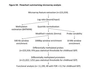
Advanced Discriminator Circuit and TDC System for Belle-II RPC Frontend
Introducing a new discriminator circuit and TDC system featuring lower power consumption, robust protection, and modern components. The system includes a high-performance FPGA TDC with low latency, synchronized edge detectors, and data concentrators. Developed for Belle-II RPC frontend with reusability of existing components.

Advanced Discriminator Circuit and TDC System for Belle-II RPC Frontend
E N D
Presentation Transcript
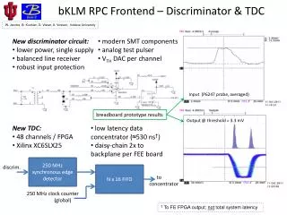
bKLMRPC Frontend – Discriminator & TDC W. Jacobs, B. Kunkler, G. Visser, A. Vossen, Indiana University • New discriminator circuit: • lower power, single supply • balanced line receiver • robust input protection • modern SMT components • analog test pulser • VTH DAC per channel Input (P6247 probe, averaged) breadboard prototype results Output @ threshold = 3.3 mV • New TDC: • 48 channels / FPGA • Xilinx XC6SLX25 • low latency data concentrator (≈530 ns†) • daisy-chain 2x to backplane per FEE board 250 MHz synchronous edge detector discrim. N x 16 FIFO to concentrator 250 MHz clock counter (global) † To FE FPGA output; not total system latency
bKLMRPC Frontend – System & Status System Block Diagram (per crate, 16x) JTAG (chipscope) output • Stackable prototype board now in final stages of layout; fab 12/2011 • Plan to run tests with bKLM modules in Belle, early 2012 • 2 – 3 layers read out (synchronously) 48 channels input • Existing Belle bKLM crates and RPC signal cables are re-used. • Each Belle-II RPC FEE crate consists of thirteen FEE boards and one concentrator board. 6U x 160mm. • One FEE board signal connector handles positive detector pulses, the other negative. • Crate uses VME-J1 backplane in point-to-point protocol – five data lines dedicated to each FEE board. No added latency from bus protocols or sharing. • Belle-II bKLM RPC overall uses 16 fibers (Belle2Link) to DAQ and 16 fibers feeding hit info to trigger decision logic tree.