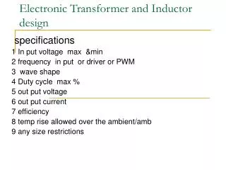
Switchmode Transformer Design
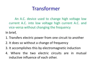
Switchmode Transformer Design. By: Rizwan Khalid. Outline. Introduction Theory Pexpert simulations Applications Conclusion . Introduction. The main objective is to design a switchmode transformer. The switchmode transformer is a very essential part of the design.


Switchmode Transformer Design
E N D
Presentation Transcript
Switchmode TransformerDesign By: Rizwan Khalid
Outline • Introduction • Theory • Pexpert simulations • Applications • Conclusion
Introduction • The main objective is to design a switchmode transformer. • The switchmode transformer is a very essential part of the design. • The reason is that it will determine the cost and the efficiency of a modern switchmode supply. • The major dilemma that the designers our facing is the transformer design process is the most poorly understood area of switchmode design.
Theory • To design a switchmode transformer we have to keep in mind the following major parameters: • The transformer size • The flux-density swing • Turns • Core loss • Copper loss • Skin effects
Transformer Size • Transformer size is directly proportional to the temperature and power losses. • To decrease the transformer size we will have to some how decrease the power losses and find some way to extract the heat from the transformer. • For example by using superconductors, amorphous alloys and heat pipes miniature, high efficiency transformers can be produced.
Optimum Efficiency • The optimum efficiency occurs when core and copper losses are minimized. The problem is that the core loss and the copper loss are inversely proportional.
Optimum Core Size and Flux Density Swing • Since there are so many interdependent variables it is very difficult for the designer to make an optimum core size and flux density choice. • The nomogram provided in figure 2 has a comprehensive approach in trying to find the core size and flux density.
Pexpert verification (Cont’d) Figure 1
Pexpert verification (Cont’d) To verify that the change in power will result in a change in core size Pexpert is used. At a power of 50 watts as shown in figure 1 we get a power loss of 1.577
In figure 3, if we change the power to 30 Watts keeping everything else the same the power loss is 1.15 W
Pexpert verification (cont’d) • If we change the frequency in figure 3 from 100kHz to 80kHz and leave everything else the same the power loss increases as a result the core size increases. Therefore reducing frequency increases core size.
Calculating Core Size in terms of Area Product • The area product (AP) is the product of the winding window area and the cross sectional area of the core. • AP = {(11.1* Pin) / (K’*∆B *f)}1.143 • where AP = area product, cm4 • Pin = input power, W • K’ = overall copper utilization factor. • ∆B = flux density swing, T • f = frequency, Hz
Flux Density Swing ∆B • As mentioned before, to obtain maximum efficiency the ∆B should be selected such that the core loss is equal to the copper loss. • From figure 2 we can see that the increase in flux density increases the power losses of a particular topology.
Calculation of Primary Turns • A core loss limited design is to have the maximum flux density swing and hence the minimum number of primary turns at high frequencies. • If we use a smaller number of primary turns to get minimum copper losses we will encounter saturation in the core. • Core saturation must be avoided because the impedance of the primary winding in the saturation region will be equal to the Dc winding resistance which is a very low resistance. This low resistance will allow high currents which will damage the transformer.
Calculating Secondary Turns • After calculating the primary turns the number of secondary turns is calculated by primary to secondary voltage ratio which differs for different topologies. • It is better to first calculate the secondary turns and from there calculate the primary turns to avoid partial secondary turns.
Wire sizes • Since we have already selected a core size and calculated the primary and secondary turns, it is better at this stage to select a wire size that will make the best use of the available window area. • Before we select the wire size we have to take in consideration of skin and proximity effects.
Skin Effects and Optimum Wire Thickness • In practical application the minimum Fr ratio will approach 1.5. • In order to achieve this ratio the wire diameter or the strip thickness must be optimized to a particular operating frequency and number of layers • The selection of the size should also be based on a minimum number of layers because it improves the Fr ratio and reduces the leakage inductance.
Verify Results • In the final analysis the core losses and copper losses are calculated to verify if the design is fully optimized. • In the final design the temperature should be checked by calculating the losses and should be under 30 C • After that we can find the efficiency ŋ from the following equation • ŋ = (output power *100)/ (Output power + losses).
Conclusion • I was able to verify the change in power losses in Pexpert. • In my opinion core size is the most important factor that determines transformer size. • We have to be very careful while we are choosing the flux density.