Download
1 / 28
280 likes | 456 Views
PANDA electromagnetic calorimeters. Pavel Semenov IHEP, Protvino on behalf of the IHEP PANDA group INSTR08 28 Feb - 05 Mar 2008. Outline. PANDA detector setup Target Spectrometer EMC PANDA gamma irradiation facility at IHEP Light output at -20 ° C

E N D
PANDA electromagnetic calorimeters Pavel Semenov IHEP, Protvino on behalf of the IHEP PANDA group INSTR08 28 Feb - 05 Mar 2008
Outline • PANDA detector setup • Target Spectrometer EMC • PANDA gamma irradiation facility at IHEP • Light output at -20°C • Radiation hardness measurements at -20°C • Forward Spectrometer EMC • EMC prototype module parameters • Prototype testbeam results for energy and position resolution • MC studies to find optimal parameters Pavel Semenov, INSTR08@BINP, Novosibirsk
PANDA EM Calorimeters placement TS EMC FS EMC Pavel Semenov, INSTR08@BINP, Novosibirsk
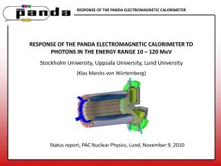
Target spectrometer EMC • Requirements • Geometrical coverage close to 4π • Compact size • Fast signal, good time resolution • Low energy threshold (10 MeV) of photon detection • Excellent position and energy resolutions • PbWO4 (PWO) crystal as a good candidate for the TS EMC • 21 mm x 21 mm x 20 cm barrel cell size (front), 25 mm x 25 mm x 20 cm endcap cell cize • ~17000 crystals (96 % of 4 π) • Improved light output is needed to reach excellent resolution and low threshold • Calorimeter operates at low temperature (about -200C, factor of 3 increase of light output) • PWO-II: enhanced light output PWO (~20 phe/MeV) • PWO radiation hardness at room temperature is not a problem for PANDA (dose rates not more then a few rad/hour). But there were no data for PWO radiation hardness properties at -20 0C Pavel Semenov, INSTR08@BINP, Novosibirsk
PANDA-IF at IHEP features • Crystal holder (Cu plate with heat-exchanging system) for 5 crystals • Cryothermostat (LAUDA RC6CP) capable of temperature stabilization in the region of -35 °C --- +200 °C • LED system to monitor PMT gain and crystals transparency in blue and red part of the visible spectrum • Cs137 gamma source gives irradiation dose rate 100 rad/h and below • Monitoring of temperature sensors ( Pt100 and Pt1000 class A ) at 6 points (2 on crystals) Pavel Semenov, INSTR08@BINP, Novosibirsk
PANDA-IF picture Cryothermostat Crystal box Pavel Semenov, INSTR08@BINP, Novosibirsk
PWO properties studies at low temperatures Light output change before the irradiation with temperature change from +18.5 0Cto -19.4 0C Radiation hardness studies of PWO-II at PANDA dose rates (max 2 rad/hour) and -20 0C showed 20%-35% drop of DC output signal after 300-400 hours of irradiation Pavel Semenov, INSTR08@BINP, Novosibirsk
PWO light transmittance recovery at -200C Paper: First study of radiation hardness of lead tungstate crystals at low temperatures Published at NIM A Vol 582/2 pp 575-580 Pavel Semenov, INSTR08@BINP, Novosibirsk
Radiation hardness studies of PWO-II (high dose rate) Still factor 1.4 enhancement of light output Pavel Semenov, INSTR08@BINP, Novosibirsk
Forward Spectrometer EMC • 7 meters from the interaction point • Covers 3 m2 • Fine segmented sampling calorimeter with light collection by optical WLS fibers passing through holes in the scintillator and lead layers (shashlyk type) • Not in magnetic field (PMT as photodetector) • Working energy range 10 MeV – 10 GeV Pavel Semenov, INSTR08@BINP, Novosibirsk
Testbeam setup • Spectrometer consisted of 4 drift chamber stations and a magnet to measure beam particle momentum precisely • Calorimeter prototype installed on a movable platform DC1 M14 DC2 DC3 ECAL prototype Beam DC4 Pavel Semenov, INSTR08@BINP, Novosibirsk
Shashlyk prototype module parameters 9 modules assembled in matrix 3x3 • 380 layers of 0.3-mm lead and 1.5-mm scintillator, total length 680 mm • Transverse size 110x110 mm2 • Effective Moliere radius: RM=59 mm • Effective radiation length: X0=34 mm • Total radiation length: 20X0 • Light collection: 144 (1212) fibers BCF-91A (1.2 mm) • PMT Hamamtsu R5800 as photodetectors Pavel Semenov, INSTR08@BINP, Novosibirsk
Shashlyk modules production Pavel Semenov, INSTR08@BINP, Novosibirsk
Shashlyk prototype pictures 3x3 matrix of shashlyk modules and PMT attached to the modules Pavel Semenov, INSTR08@BINP, Novosibirsk
Minimum ionizing particle peak Pavel Semenov, INSTR08@BINP, Novosibirsk
Energy Resolution dependence on energy Pavel Semenov, INSTR08@BINP, Novosibirsk
Energy Resolution parameterization σE /E = a/E b/√E c [%], E in GeV Experiment data fit: MC data fit: a = 3.5 ± 0.3 a = 0.0 b = 2.8 ± 0.2 b = 3.0 ± 0.3 c = 1.3 ± 0.04 c = 1.1 ± 0.7 Good agreement with MC without noise term. Good agreement with previous studies of similar sampling modules at lower energies (2.9%/ √E at 220-370 MeV: Test beam study of the KOPIO shashlyk calorimeter prototype, G.Atoian, S.Dhawan,V.Issakov et al. CALOR-2004 Proceedings ) Pavel Semenov, INSTR08@BINP, Novosibirsk
Measured S-curve at 19 GeV Xcog,au Real Position, cm Pavel Semenov, INSTR08@BINP, Novosibirsk
Position resolution (center) dependence on energy Pavel Semenov, INSTR08@BINP, Novosibirsk
Position resolution parameterization σx = a/√E b [mm], E in GeV Experiment data fit: MC data fit: a = 17.6 ± 0.9 a = 14.2 ± 0.6 b = 4.6 ± 0.9 b = 5.5 ± 0.9 Worst case – resolution at the module center. Resolution near the module edge is 3 times better Pavel Semenov, INSTR08@BINP, Novosibirsk
Shashlyk 8x8 cells prototype • We plan to have another shashlyk testbeam run in 2008 with prototype of 8x8 cells • Now prototype with 55mm x 55mm module sizes is under construction • Testbeam studies includes prototype energy and position resolution as well as test of π0reconstruction capabilities in the energy range up to 15 GeV Pavel Semenov, INSTR08@BINP, Novosibirsk
Conclusions • PWO-II radiation hardness at -200C studies showed deep light transmission drop (20%-35% at 2rad/hour) and low light transmission recovery rate • Testbeam studies of energy and position resolution of shashlyk prototype (110x110mm cell) results: • Energy σE /E = 3.5/E 2.8/√E 1.3 [%] • Position (at the cell center) σx = 17.6/√E 4.6 [mm] • Good agreement with MC results • Further improvement of shashlyk parameters includes prototype with 55x55 mm cell size testbeam study Pavel Semenov, INSTR08@BINP, Novosibirsk
Backup slides Pavel Semenov, INSTR08@BINP, Novosibirsk
Radiation hardness temperature dependence Pavel Semenov, INSTR08@BINP, Novosibirsk
MC shashlyk parameters • Shashlyk module geometry including holes • Tile att. length 70 cm • Fiber att length 400 cm • Reflection from tile edges diffusive • Tot. internal reflection 0.97 • Tile light output 100 eV/photon • Reemission probability in fiber 0.1 • Refraction in tiles and fibers 1.59 Pavel Semenov, INSTR08@BINP, Novosibirsk
S-curve MC (0.5 – 10 GeV) Pavel Semenov, INSTR08@BINP, Novosibirsk
PANDA-IF electronics • Based on i7k (ICP DAS) modules with RS485 interface • Short connections (0.5 m) from PMT and temperature sensors to read-out electronics • Temperature measurements with an accuracy better than 0.03 °C • DC current measurements accuracy up to nA • LED signals in DC mode – measurement of the mean current thru 10 kΩ generated by a bunch of pulses • HV for PMTs: LeCroy1440 system Pavel Semenov, INSTR08@BINP, Novosibirsk
PANDA-IF electronics diagram RS485 bus RS485/RS232 converter 7013 PT1000 7017 ADC 7042 DO RS232 VME 7 signal lines DAQ computer Linux PT1000 LED generator CAMAC LAUDA Opt. fibers Shutter RS232- CL Crystal Box Cs137 LRS1440 HV system HV Control room Irradiation facility Shutter digital control lines Pavel Semenov, INSTR08@BINP, Novosibirsk