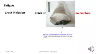
Fatigue issues
Fatigue issues. 13 kA interconnection one load, resistance SC to SC. SC joint: combined electrical and mechanical tests. Aim Evaluate possible deterioration of the electrical quality of the joint because of the mechanical efforts How Measure the resistance of standard joint

Fatigue issues
E N D
Presentation Transcript
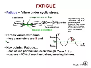
SC joint: combined electrical and mechanical tests • Aim • Evaluate possible deterioration of the electrical quality of the joint because of the mechanical efforts • How • Measure the resistance of standard joint • Submit the same joints to tensile load (500 N, 1000 N, 5000 N) • Re-measure the resistance EDMS No. 1086056
Results 1.9 K EDMS No. 1086056
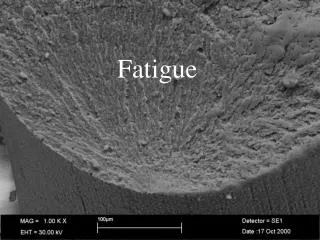
A fatigue test on a good Cu-Cu connection for tensile efforts EDMS No. 1086056
Mechanical test procedure and acceptance limits • At room temperature • Fatigue life cycle: 5000 cycles from 20 N to 240 N • Tensile test: minimum force for joint breakage 900 N • At 4.2 K • Fatigue life cycle: 5000 cycles from 40 N to 510 N • Tensile test: minimum force for joint breakage 1000 N • Total number of tests performed: 34 R.T., 46 4.2 K EDMS No. 1086056
Production samples The check was performed by the execution, by the same operators using that specific machine, of two production samples. After a visual inspection, the samples were tested electrically at the CERN cryolab and thereafter mechanically at the EIG (Ecoled’Ingénieurs de Genève). Important: no one of the joints tested was broken during the tests. A test was stopped because 1) An upper test limit due to the test set up was reached ( typically 2 KN for the 4.2 K and 5 KN for the R.T. tests) 2) A discontinuity on the loading curve was observed (see case I and case II) and that value was declared the limit of the joint EDMS No. 1086056
Test equipment EIG EDMS No. 1086056
Tensile test R.T. EDMS No. 1086056
Tensile test 4.2 K EDMS No. 1086056
A fatigue test on a good Cu-Cu connection for tensile efforts EDMS No. 1086056
A fatigue test on a good Cu-Cu connection for tensile efforts EDMS No. 1086056
Effect of fatigue on electrical resistanceCycles at 77K R measurement at RT F2 broke after 37 cycles at 6.8KN (tensile strenght7-7.9KN-> kept 85% of strength after 300 cycles )
Sample 2 of fast brazing technique has been cycled in LN2 at 6800 N, rupture occurred after 37 cycles • Fractography Fast brazing, 15 mm brazed length: Fatigue striations Cracks
Conclusion on low cycle effect • The performed fatigue tests indicate that • The soldering should withstand the loads originated from the thermal contraction mismatch without significant increase in the connection resistance • The possible crack propagation coming from local defect seems to be active only when we go over the yield strength • We do not have direct estimation of the effect of • Microstructure coarsening • Steady state creep at low temperature BUT • Coarsening effect: it should be linked to the diffusion coefficient D=D0 exp-(Q/kT) and therefore in our case effect limited • Steady state creep. Creep should strongly decrease at T<0.5THOM (456K->T<228K) • Further test with pure thermal cycling will be performed on the final solution
Tensile-ShearStrengthAfter TC • Tensile-shear strength was tested after thermal cycling for different shunt samples soldered with Sn60-Pb40 Impact of thermal cycling rather limited Mob 39 Kester Courtesy A. Gerardin
Effect soldering temperature on intermetallic thickness(mech. Properties) [19] EDMS No. 1086322
Effect of intermetallic on mech. Properties III [19] EDMS No. 1086322
Aging [15,17] • Effect of aging on solder (in function of the Sb content ) • Effect ofintermetallic thickness on mech. properties EDMS No. 1086322
Joint strength vs. intermetallic and thermal aging [2] Furthermore, the activation energy for growth of Cu3Sn on polycrystalline copper was found to be 1.27 eV and for Cu6Sn5 it was 0.47 eV, thus explaining the slower growth rate of Cu3Sn. The Cu–Snintermetallic layer growth behavior can be described by one-dimensional growth parameter, Y, which is related to the square root of the aging time. Y=[Dt]^0.5 where D is the diffusion coefficient and t, the aging time. The diffusion coefficient is given by an Arrhenius expression, D=D0 exp-(Q/kT) where D0 is the diffusion constant; Q, the activation energy; k, the Boltzmann constant and T, the absolute temperature. EDMS No. 1086322
Joint strength vs. intermetallic and thermal aging [15] The formation of inter-metallic is an exothermic reaction therefore it progresses with time. Aging causes coarsening of the structure that brings to • lower capacity to absorb deformation • fragilization-> crack propagation increase speed • But no decrease of the max load As the coarsening of the structure is dominated by the diffusion coefficient and by the activation energy the coarsening effect for our use should be limited EDMS No. 1086322
Properties in function of solder composition vs aging [3] EDMS No. 1086322
Fatigue effects on joint EDMS No. 1086322
Isothermal fatigue life [15] EDMS No. 1086322
Isothermal fatigue life II [15] EDMS No. 1086322
Fatigue and crack growth [2] • For low frequency and high R (σmax/σmin) crack growth is time dominated-> creep • For high frequency and low R> LFM explain the behavior EDMS No. 1086322
Fatigue Vs. soldering process [17,18,20] It can be obtained by rapid cooling going away from the lamellar eutectic structure towards the fine grain structure. This allows intergranular creep. This structure is not stable evolving towards a coarser structure/ larger grains have lowed free energy but the rate of change is proportional to temperature In the superplastic region larger strain are accepted without fracture [20] In samples quenched after 1 min only Cu6Sn5 was found. In samples quenched after 5 minutes also Cu3Sn was there EDMS No. 1086322
Fatigue Vs. soldering process [17,18] EDMS No. 1086322
Fatigue vs. environment [18] The positive effect of vacuum (no oxygen) on the crack propagation is known and seems to be confirmed for soldering alloys EDMS No. 1086322
Fracture mode of Sn-Pb/copper joints [17] • In tensile the fracture happens through the solder bulk • But in the case of eutectic cooled at slow rate the fracture takes place in the fragile intermetallic • Tests at 77K show displacement of the fracture line between intermetallic and solder and this seems linked to the effect of the anisotrpic crystal thermal contraction of the metallic Sn (tetragonal) EDMS No. 1086322
Intermetallic properties [18,21] Cu6Sn5 melts at 415 ⁰ C CuSn3 melts at 670 ⁰ C EDMS No. 1086322
References • Measurements of mechanical properties of electronic materials at temperature down to 4.2 K Cryogenics 48 pag 487-510 • [2] fatigue crack growth behavior of Sn-Pb engineering fracture mechanics 70 pag 2187 2197 • [3] tensile fracture of tin-lead solder joints in copper material science and engineering A 379 pag. 277-285 • [4] deformation analysis of lap-shear testing of solder joints ActaMaterialia 32 2633-2642 • Deformation of solder joints under current stressing Solids and structure 41 4959-4973 • [6] strengthening of Sn60-Pb40 solder alloy by adding traces of La Materials letters 52 319-322 • [7]Improvement of micro structure stability, mechanical properties and wetting prop of Sn-AG-Cu lead free solder adding rare earth elements journal of alloy and compounds 376 170-175 • [8] comparative study of wetting behavior of sn-Zn and Sn-Pb microelectronics journal 37 705-713 • [9] tests for tin lead solders and solder joints bureau of mine report of investigation number 6963 • [10] tensile and shear properties of several solders at cryogenic temperature national aerospace engineering and manufacturing meeting Los Angeles oct 8-12 1962 • [11]design criteria for solders in cryogenic environments • [12] A brief study of soft soldering. The institution of production engineers • [13] enhancement of wettability and solder joint reliability by AG coating Alloys and compounds 360 217 224 • [14]microstructure and metallic growth effect on shear strength …. Material science and engineering A 307 42-50 • [15]SMT soldering handbook Newness • [16] ASM welding brazing and soldering handbook • [17] The mechanics of solder alloy: wetting and spreading Yost, Hosking, Frear • [18] The mechanics of solder alloy: interconnects Frear, Morgan, Burchett, Lau • [19] AWS manuel de brasagetendre • [20] Solder joint creep and stress relaxation dependence on construction and environmental stress parameter • [21] solders and soldering Materials, Design, Production and Analysis for reliable bonding. H. Manko McGraw-Hill • [22] Tin solders: A modern study of the properties of tin solders and soldered joints S.J. Nightingale • [23]Development of stress strain curves for In80Pb15ag5 journal of electronic materials vol 28 page 1084-1087 • [24] Deformation properties of Indium based solders at 294 and 77 K Cryogenics 1991 vol 31 page 159-163 • [25] Mechanical properties of In based Eutectic alloy solders used in Josephson packaging Cryogenics May 1984 pag 261-265 • [26] Measured Performance of Different Solders in Bi2223/Ag Current Leads IEEE TRANSACTIONS ON APPLIED SUPERCONDUCTIVITY, VOL. 18, NO. 2, JUNE 2008 • [27] Magnetoresistance of selected Sn- and Pb-based solders at 4.2 K Material Letters 57 787-793 • [28] Mechanical behavior of microelectronics and power electronics under high current density Hua Ye PhD November 2004 University of Buffalo EDMS No. 1086322