Download
1 / 13
130 likes | 228 Views
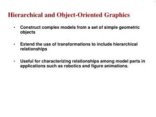
Chapter 8 Hierarchical and Object-oriented Graphics. Symbols and Instances Hierarchical Models Robot Arm Trees and Traversal Use of Tree Data Structures Animation Graphical Objects Scene Graphs Other Tree Structures Graphics and the Web

E N D
Chapter 8 Hierarchical and Object-oriented Graphics • Symbols and Instances • Hierarchical Models • Robot Arm • Trees and Traversal • Use of Tree Data Structures • Animation • Graphical Objects • Scene Graphs • Other Tree Structures • Graphics and the Web “Models are abstractions of the world (real or virtual)” - p.333
Symbols and Instances • Symbol • geometric objects, fonts, and application-dependent sets of graphical objects such as standard symbols used in circuit design (usually represented at a convenient size and orientation) • Figure 8.1 • Instance transformation • place instances of each symbol in the model, with the desired size, and orientation, and at the desired location • a concatenation of a translation, a rotation, and a scale (M = TRS, Figure 8.2) • Symbol-instance transformation table (Figure 8.3)
Hierarchical Models (1) • Example • a car composed of the chassis and four wheels (Figure 8.4) • a simple animation (Figure 8.5) • not good code • no relationships among components • relationships • movements of chassis and wheels • 4 wheels are identical with different positions main() { float s= ….; /* speed */ float d[3]={…} /* direction */ draw_right_front_wheel(s,d); draw_left_front_wheel(s,d); draw_right_rear_wheel(s,d); draw_left_rear_wheel(s,d); draw_chassis(s,d); }
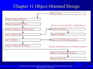
Hierarchical Models (2) • Relationships among Parts of the Models • tree (Figure 8.6) • directed acyclic graph (DAG) (Figure 8.7)
Robot Arm (1) • A simple robot arm • Figure 8.8(a) • 3 parts (Figure 8.8(b)) • 3 DOF described by joint angles
Robot Arm (2) • Transformation (Figures 8.8 and 8.9) • base : Ry() • lower arm: Ry()T(0, h1, 0)Rz() • upper arm : Ry()T(0, h1, 0)Rz()T(0, h2, 0)Rz() • Tree structures • Figures 8.10 and 8.11 • Program • robot.c in Appendix A
Tree and Traversal (1) • A human figure example • Figures 8.12 and 8.14 • neck joint has 2 DOF and others 1 DOF
Tree and Traversal (2) • Tree traversal • both DFS and BFS applicable • in this book, pre-order traversal • left-to-right and DFS • implementation • stack-based vs. recursion • A stack-based traversal • function figure() • use of glPushMatrix and glPopMatrix • concerning attributes (color and so on) • glPushAttrib and glPopAttrib • limitation • hard-wired (explicit codes for objects)
Use of Tree Data Structures (1) • Left-child right sibling structure • Node structure typedef struct treenode { GLfloat m[16]; void (*f)(); struct treenode *sibling; struct treenode *child; } treenode; • For our figure (Figure 8.12) treenode torso_node, head_node, lua_node, rua_node, lll_node, rll_node, lla_node, rla_node, rul_node, lul_node; • torso_node glLoadIdentity(); glRotatef(theta[0], 0.0, 1.0, 0.0); glGetFloatv(GL_MODELVIEW_MATRIX, torso_mode.m); torso_node.f = torso; torso_node.sibling = NULL; torso_node.child = &head_node;
Use of Tree Data Structures (2) • Left-upper arm node glLoadIdentity(); glTranslatef(-(TORSO_RADIUS+UPPER_ARM_RADIUS), 0.9*TORSO_HEIGHT, 0.0); glRotatef(theta[3], 1.0, 0.0, 0.0); glGetFloatv(GL_MODELVIEW_MATRIX, lua_node.m); lua_node.f = left_upper_arm; lua_node.sibling = &rua_node; lua_node.child = &lla_node; • Tree traversing (preorder) void traverse(treenode* root) { if(root==NULL) return; glPushMatrix(); glMultMatrixf(root->m); root->f(); if(root->child!=NULL) traverse(root->child); glPopMatrix(); if(root->sibling!=NULL) traverse(root->sibling); }
Use of Tree Data Structures (3) • Mouse callback function void mouse(int btn, int state, int x, int y) { if(btn==GLUT_LEFT_BUTTON && STATE == GLUT_DOWN) { theta[angle] += 5.0; if(theta[angle] > 360.0) theta[angle] -= 360.0; } if(btn==GLUT_LEFT_BUTTON && STATE == GLUT_DOWN) { theta[angle] -= 5.0; if(theta[angle] < 360.0) theta[angle] += 360.0; } glPushMatrix(); switch(angle) { case 0: glLoadIdentity(); glRotatef(theta[0], 0.0, 1.0, 0.0); glGetFloatv(GL_MODELVIEW_MATRIX, torso_node.m); break; /* other cases */ glPopMatrix(); glutPostRedisplay(); }
Use of Tree Data Structures (4) • Display callback function void display(void) { glClear(GL_COLOR_BUFFER_BIT|GL_DEPTH_BUFFER_BIT); glLoadIdentity(); traverse(&torso_node); glutSwapBuffers(); } • Dynamic editing of model is possible • Eg) adding a dynamic node typedef treenode* tree_ptr; tree_ptr torso_ptr; torso_ptr = malloc(sizeof(treenode)); glLoadIdentity(); glTranslatef(-(TORSO_RADIUS+UPPER_ARM_RADIUS), 0.9*TORSO_HEIGHT, 0.0); glRotatef(theta[3], 1.0, 0.0, 0.0); glGetFloatv(GL_MODELVIEW_MATRIX, lua_ptr->m); lua_ptr->f = left_upper_arm; lua_ptr->sibling = rua_ptr; lua_ptr->child = lla_ptr; traverse(torso_ptr);
Animation • Animation • time sequence of visual changes in a scene • articulated figures • models consisting of rigid parts connected by joints • change the parameters such as joint angles over time change the motion of the model • kinematics • study to describe the position of parts of the model based on the joint angles p = f() p : position : joint angle • inverse kinematics (inverse dynamics) • given desired state of model, find the joint angles to achieve the position = g(p) • very difficult task because of non-unique inverses • key-frame animation • the animator positions the objects at set of times - the key frames • inbetweening • the process to fill the remaining frames -> interpolation • difficulties: matching of vertices • morphing