Download
1 / 70
700 likes | 851 Views
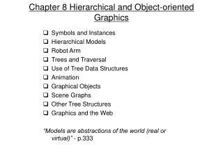
Hierarchical and Object-Oriented Graphics. Construct complex models from a set of simple geometric objects Extend the use of transformations to include hierarchical relationships Useful for characterizing relationships among model parts in applications such as robotics and figure animations.

E N D
Hierarchical and Object-Oriented Graphics • Construct complex models from a set of simple geometric objects • Extend the use of transformations to include hierarchical relationships • Useful for characterizing relationships among model parts in applications such as robotics and figure animations.
Symbols and Instances • A non-hierarchical approach which models our world as a collection of symbols. • Symbols can include geometric objects, fonts and other application-dependent graphical objects. • Use the following instance transformation to place instances of each symbol in the model. • The transformation specify the desired size, orientation and location of the symbol.
Hierarchical Models • Relationships among model parts can be represented by a graph. • A graph consists of : • A set of nodes or vertices. • A set of edges which connect pairs of nodes. • A directed graph is a graph where each of its edges has a direction associated with it.
Trees and DAG: Trees • A tree is a directed graph without closed paths or loops. • Each tree has a single root node with outgoing edges only. • Each non-root node has a parent node from which an edge enters. • Each node has one or more child nodes to which edges are connected. • A node without children is called a terminal node or leaf.
Trees and DAGS: Trees root node edge node leaf
Trees and DAG: DAG • Storing the same information in different nodes is inefficient. • Use a single prototype for multiple instances of an object and replace the tree structure by the directed acyclic graph (DAG). • Both trees and DAG are hierarchical methods of expressing relationships.
Example: A Robot Arm • The robot arm is modeled using three simple objects. • The arm has 3 degrees of freedom represented by the 3 joint angles between components. • Each joint angle determines how to position a component with respect to the others.
Robot Arm: Base • The base of the robot arm can rotate about the y axis by the angle . • The motion of any point p on the base can be described by applying the rotation matrix
Robot Arm: Lower Arm • The lower arm is rotated about the z-axis by an angle , which is represented by • It is then shifted to the top of the base by a distance , which is represented by . • If the base has rotated, we must also rotate the lower arm using . • The overall transformation is .
Robot Arm: Upper Arm • The upper arm is rotated about the z-axis by the angle , represented by the matrix . • It is then translated by a matrix relative to the lower arm. • The previous transformation is then applied to position the upper arm relative to the world frame. • The overall transformation is
OpenGL Display Program display() { glRotatef(theta, 0.0, 1.0, 0.0); base(); glTranslatef(0.0, h1, 0.0); glRotatef(phi, 0.0, 0.0, 1.0); lower_arm(); glTranslatef(0.0, h2, 0.0); glRotatef(psi, 0.0, 0.0, 1.0); upper_arm(); }
Tree Representation • The robot arm can be described by a tree data structure. • The nodes represent the individual parts of the arm. • The edges represent the relationships between the individual parts.
Information Stored in Tree Node • A pointer to a function that draws the object. • A homogeneous coordinate matrix that positions, scales and orients this node relative to its parent. • Pointers to children of the node. • Attributes (color, fill pattern, material properties) that applies to the node.
Trees and Traversal • Perform a tree traversal to draw the represented figure. • Two possible approaches • Depth-first • Breadth-first • Two ways to implement the traversal function • Stack-based approach • Recursive approach
Example: A Robot Figure • The torso is represented by the root node. • Each individual part, represented by a tree node, is positioned relative to the torso by appropriate transformation matrices. • The tree edges are labeled using these matrices.
Stack-Based Traversal • The torso is drawn with the initial model-view matrix • Trace the leftmost branch to the head node • Update the model-view matrix to • Draw the head • Back up to the torso node. • Trace the next branch of the tree. • Draw the left-upper arm with matrix • Draw the left-lower arm with matrix • Draw the other parts in a similar way.
OpenGL Implementation: Head Figure() { glPushMatrix(); torso(); glTranslate glRotate3 head(); glPopMatrix();
OpenGL Implementation: Left Arm glPushMatrix(); glTranslate glRotate3 Left_upper_arm(); glTranslate glRotate3 Left_lower_arm(); glPopMatrix(); }
Push and Pop Operations • glPushMatrix puts a copy of the current model-view matrix on the top of the model-view-matrix stack. • glTranslate and glRotate together construct a transformation matrix to be concatenated with the initial model-view matrix. • glPopMatrix recovers the original model-view matrix. • glPushAttrib and glPopAttrib store and retrieve primitive attributes in a similar way as model-view matrices.
Recursive Approach • Use a left-child right-sibling structure. • All elements at the same level are linked left to right. • The children are arranged as a second list from the leftmost child to the rightmost. root
FirstChild pointer: arrow that points downward NextSibling pointer: arrow that goes left to right
Data Structure for Node Typedef struct treenode { GLFloat m[16]; void (*f)(); struct treenode *sibling; struct treenode *child; } treenode;
Description of Data Structure Elements • m is used to store a 4x4 homogeneous coordinate matrix by columns. • f is a pointer to the drawing function. • sibling is a pointer to the sibling node on the right. • child is a pointer to the leftmost child.
OpenGL Code: Torso Node Initialization glLoadIdentity(); glRotatef(theta[0], 0.0, 1.0, 0.0); glGetFloatv(GL_MODELVIEW_MATRIX,torso_node.m); Torso_node.f=torso; Torso_node.sibling=NULL; Torso_node.child= &head_node;
OpenGL Code: Upper Left Arm Node Initialization glLoadIdentity(); glTranslatef(-(TORSO_RADIUS+UPPER_ARM_RADIUS), 0.9*TORSO_HEIGHT, 0.0); glRotatef(theta[3], 1.0, 0.0, 0.0); glGetFloatv(GL_MODELVIEW_MATRIX, lua_node.m); Lua_node.f=left_upper_arm; Lua_node.sibling= &rua_node; Lua_node.child= &lla_node;
OpenGL Code: Tree Traversal Void traverse (treenode *root) { if (root==NULL) return; glPushMatrix(); glMultMatrixf(root->m); root->f(); if (root->child!=NULL) traverse(root->child); glPopMatrix(); if (root->sibling!=NULL) traverse(root->sibling); }
Animation • Objective: to model a pair of walking legs.
Animation: Walking Legs • Rotation of the base will cause rotation of all the other parts. • Rotation of other parts will only affect themselves and those lower parts attached to them.
Definition of Body Metrics • The relative body metrics are defined in the file model.h. • The main parts include the base and the two legs. #define TORSO_HEIGHT 0.8 #define TORSO_WIDTH TORSO_HEIGHT*0.75 #define TORSO_DEPTH TORSO_WIDTH/3.0 #define BASE_HEIGHT TORSO_HEIGHT/4.0 #define BASE_WIDTH TORSO_WIDTH #define BASE_DEPTH TORSO_DEPTH
Drawing the Base void Draw_Base(void) { glPushMatrix() ; glScalef(BASE_WIDTH,BASE_HEIGHT, BASE_DEPTH); glColor3f(0.0,1.0,1.0) ; glutWireCube(1.0) ; glPopMatrix() ; }
Drawing the Upper Leg void Draw_Upper_Leg(void) { glPushMatrix() ; glScalef(UP_LEG_JOINT_SIZE,UP_LEG_JOINT_SIZE,UP_LEG_JOINT_SIZE); glColor3f(0.0,1.0,0.0) ; glutWireSphere(1.0,8,8) ; glPopMatrix() ; glColor3f(0.0,0.0,1.0) ; glTranslatef(0.0,- UP_LEG_HEIGHT * 0.75, 0.0) ; glPushMatrix() ; glScalef(UP_LEG_WIDTH,UP_LEG_HEIGHT,UP_LEG_WIDTH) ; glutWireCube(1.0) ; glPopMatrix() ; }
Drawing the Whole Leg void Draw_Leg(int side) { glPushMatrix() ; glRotatef(walking_angles[side][3],1.0,0.0,0.0) ; Draw_Upper_Leg() ; glTranslatef(0.0,- UP_LEG_HEIGHT * 0.75,0.0) ; glRotatef(walking_angles[side][4],1.0,0.0,0.0) ; Draw_Lower_Leg() ; glTranslatef(0.0,- LO_LEG_HEIGHT * 0.625, 0.0) ; glRotatef(walking_angles[side][5],1.0,0.0,0.0) ; Draw_Foot() ; glPopMatrix() ; }
Drawing the Complete Model void Draw_Base_Legs(void) { glPushMatrix() ; glTranslatef(0.0,base_move,0.0) ; Draw_Base() ; glTranslatef(0.0,-(BASE_HEIGHT),0.0) ; glPushMatrix() ; glTranslatef(TORSO_WIDTH * 0.33,0.0,0.0) ; Draw_Leg(LEFT) ; glPopMatrix() ; glTranslatef(-TORSO_WIDTH * 0.33,0.0,0.0) ; Draw_Leg(RIGHT) ; glPopMatrix() ; }
Codes for Calculating Vertical Displacement double find_base_move(double langle_up, double langle_lo, double rangle_up, double rangle_lo) { double result1, result2, first_result, second_result, radians_up, radians_lo; radians_up = (PI*langle_up)/180.0 ; radians_lo = PI*(langle_lo-langle_up)/180.0 ; result1 = (UP_LEG_HEIGHT + 2*UP_LEG_JOINT_SIZE) * cos(radians_up); result2 = (LO_LEG_HEIGHT+2*(LO_LEG_JOINT_SIZE+FOOT_JOINT_SIZE) +FOOT_HEIGHT)* cos(radians_lo) ; first_result = LEG_HEIGHT - (result1 + result2) ;
Codes for Calculating Vertical Displacement radians_up = (PI*rangle_up)/180.0 ; radians_lo = PI*(rangle_lo-rangle_up)/180.0 ; result1 = (UP_LEG_HEIGHT + 2*UP_LEG_JOINT_SIZE) * cos(radians_up) ; result2 = (LO_LEG_HEIGHT +2*(LO_LEG_JOINT_SIZE+FOOT_JOINT_SIZE) +FOOT_HEIGHT)* cos(radians_lo) ; second_result = LEG_HEIGHT - (result1 + result2) ; if (first_result <= second_result) return (- first_result) ; else return (- second_result) ; }
Key-Frame Animation • The more critical motions of the object is shown in a number of key frames. • The remaining frames are filled in by interpolation (the inbetweening process) • In the current example, inbetweening is automated by interpolating the joint angles between key frames.
Interpolation Between Key Frames • Let the set of joint angles in key frame A and key frame B be and respectively. • If there are M frames between key frame A and B, let • The set of joint angles in the m-th in-between frame is assigned as
Implementation of Key-Frame Animation switch (flag) { case 1 : l_upleg_dif = 15 ;r_upleg_dif = 5 ; l_loleg_dif = 15 ;r_loleg_dif = 5 ; l_upleg_add = l_upleg_dif / FRAMES ; r_upleg_add = r_upleg_dif / FRAMES ; l_loleg_add = l_loleg_dif / FRAMES ; r_loleg_add = r_loleg_dif / FRAMES ; walking_angles[0][3] += l_upleg_add ; walking_angles[1][3] += r_upleg_add ; walking_angles[0][4] += l_loleg_add ; walking_angles[1][4] += r_loleg_add ;
Implementation of Key-Frame Animation base_move =find_base_move(walking_angles[0][3], walking_angles[0][4], walking_angles[1][3], walking_angles[1][4] ) ; frames-- ; if (frames == 0) { flag = 2 ; frames = FRAMES ;} break ; case 2:
Object-Oriented Approach • Adopt an object-oriented approach to define graphical objects. • In an object-oriented programming language, objects are defined as modules with which we build programs • Each module includes • The data that define the properties of the module (attributes). • The functions that manipulate these attributes (methods). • Messages are sent to objects to invoke a method.
A Cube Object • Non object-oriented implementation • Need external function to manipulate the variables in the data structure. Typedef struct cube { float color[3]; float matrix[4][4]; }cube;
A Cube Object • Object-oriented implementation Class cube { float color[3]; float matrix[4][4]; public: void render(); void translate (float x, float y, float z); void rotate(float theta, float axis_x, float axis_y, float axis_z); }
A Cube Object • The application code assumes that a cube instance “knows” how to perform action on itself. Cube a; a.rotate(45.0, 1.0, 0.0, 0.0); a.translate (1.0, 2.0, 3.0); a.render();
Other Examples: a Material Object • Definition of the material class • Creating an instance of the material class Class material { float specular[3]; float shininess; float diffuse[3]; float ambient[3]; } Cube a; Material b; a.setMaterial(b);
Other examples: a light source object • Definition of the light source class Class light { boolean type; boolean near; float position[3]; float orientation[3]; float specular[3]; float diffuse[3]; float ambient[3]; }