Download

1 / 20
200 likes | 332 Views
Selected Network Theorems for AC Circuits. ET 242 Circuit Analysis II. E lectrical and T elecommunication Engineering Technology Professor Jang. Acknowledgement.

E N D
Selected Network Theorems for AC Circuits ET 242 Circuit Analysis II Electrical and Telecommunication Engineering Technology Professor Jang
Acknowledgement I want to express my gratitude to Prentice Hall giving me the permission to use instructor’s material for developing this module. I would like to thank the Department of Electrical and Telecommunications Engineering Technology of NYCCT for giving me support to commence and complete this module. I hope this module is helpful to enhance our students’ academic performance.
OUTLINES • Introduction to Method of Analysis and Selected Topics (AC) • Independent Versus Dependent (Controlled) Sources • Source Conversions • Mesh Analysis • Nodal Analysis Key Words: Dependent Source, Source Conversion, Mesh Analysis, Nodal Analysis ET 242 Circuit Analysis II – Selected Network Theorems for AC Circuits Boylestad2
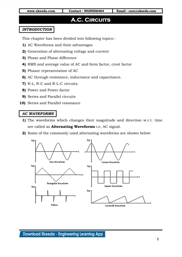
Methods of Analysis and Selected Topics (AC) For the net works with two or more sources that are not in series or parallel, the methods described the methods previously described can not be applied. Rather, methods such as mesh analysis or nodal analysis to ac circuits must be used. Independent Versus Dependent (Controlled) Sources In the previous modules, each source appearing in the analysis of dc or ac networks was an independent source, such as E and I (or E and I) in Fig. 17.1. The term independent specifies that the magnitude of the source is independent of the network to which it is applied and that the source display its terminal characteristics even if completely isolated. A dependent or controlled source is one whose magnitude is determined (or controlled) by a current or voltage of the system in which it appears. Figure 17.1Independent sources. ET 242 Circuit Analysis II – Selected Network Theorems for AC Circuits Boylestad3
Currently two symbols are used for controlled sources. One simply uses the independent symbol with an indication of the controlling element, as shown in Fig. 17.2(a). In Fig. 17.2(a), the magnitude and phase of the voltage are controlled by a voltage V elsewhere in the system, with the magnitude further controlled by the constant k1. In Fig. 17.2(b), the magnitude and phase of the current source are controlled by a current I elsewhere in the system, with the magnitude with further controlled by k2. To distinguish between the dependent and independent sources, the notation in Fig. 17.3 was introduced. Possible combinations for controlled sources are indicated in Fig. 17.4. Note that the magnitude of current sources or voltage sources can be controlled by voltage and a current. Figure 17.2Controlled or dependent sources. Figure 17.3Special notation for controlled or dependent sources. Figure 17.4Conditions of V = 0V and I = 0A for a controlled source. ET162 Circuit Analysis – Ohm’s Law Boylestad4
Source Conversions When applying the methods to be discussed, it may be necessary to convert a current source to a voltage source, or a voltage source to a current source. This source conversion can be accomplished in much the same manner as for dc circuits, except dealing with phasors and impedances instead of just real numbers and resistors. Figure 17.5Source Conversion. Independent Sources In general, the format for converting one type of independent source to another is as shown in Fig. 17.5. Ex. 17-1 Convert the voltage source in Fig. 17.6(a) to a current source. Figure 17.6Example 17.1. ET 242 Circuit Analysis II – Parallel ac circuits analysis Boylestad5
Ex. 17-2 Convert the current source in Fig. 17.7(a) to a voltage source. Figure 17.7Example 17.2. Dependent Sources For the dependent sources, direct conversion in Fig. 17.5 can be applied if the controlling variable (V or I in Fig.17.4) is not determined by a portion of the network to which the conversion is to be applied. For example, in Figs. 17.8 and 17.9, V and I, respectively, are controlled by an external portion of the network. ET 242 Circuit Analysis II – Selected Network Theorems for AC Circuits Boylestad6
Ex. 17-3 Convert the voltage source in Fig. 17.7(a) to a current source. Figure 17.8Source conversion with a voltage-controlled voltage source. Ex. 17-4 Convert the current source in Fig. 17.9(a) to a voltage source. Figure 17.9Source conversion with a current-controlled current source. ET 242 Circuit Analysis II – Parallel ac circuits analysis Boylestad2
Mesh Analysis • Independent Voltage Sources The general approach to mesh analysis for independent sources includes the same sequence of steps appearing in previous module. In fact, throughout this section the only change from the dc coverage is to substitute impedance for resistance and admittance for conductance in the general procedure. • Assign a distinct current in the clockwise direction to each independent closed loop of the network. • Indicate the polarities within each loop for each impedance as determined by the assumed direction of loop current for that loop. • Apply KVL around each closed loop in the clockwise direction. Again, the clockwise direction was chosen to establish uniformity and to prepare us for the formed approach to follow. • a. If an impedance has two or more assumed currents through it, the total current through the impedance is the assumed current of the loop in which KVL law is being applied. • b. The polarity of a voltage source is unaffected by the direction of the assigned loop currents. • 4. Solve the resulting simultaneous linear equations for the assumed loop currents. The technique is applied as above for all networks with independent sources or for networks with dependent sources where the controlling variable is not a part of the network under investigation. ET 242 Circuit Analysis II – Selected Network Theorems for AC Circuits Boylestad8
Ex. 17-5 Using the general approach to mesh analysis, find the current I1 in Fig.17.10. Figure 17.10Example 17.5. Figure 17.11Assigning the mesh currents and subscripted impedances for the network in Fig.17.10. ET 242 Circuit Analysis II – Parallel ac circuits analysis Boylestad2
Dependent Voltage Sources For dependent voltage sources, the procedure is modified as follow: • Step 1 and 2 are the same as those applied for independent sources. • Step 3 is modifies as follows: Treat each dependent source like an independent when KVL is applied to each independent loop. However, once the equation is written, substitute the equation for the controlling quantity to ensure that the unknowns are limited solely to the chosen mesh currents. • Step 4 is as before. ET 242 Circuit Analysis II – Selected Network Theorems for AC Circuits Boylestad10
Ex. 17-6 Write the mesh currents for the network in Fig. 17.12 having a dependent voltage source. Figure 17.12Applying mesh analysis to a network with a voltage-controlled voltage source. • Independent Current Sources For independent current sources, the procedure is modified as follow: • Step 1 and 2 are the same as those applied for independent sources. • Step 3 is modifies as follows: Treat each current source as an open circuit and write the mesh equations for each remaining independent path. Then relate the chosen mesh currents to the dependent sources to ensure that the unknowns of the final equations are limited to the mesh currents. • Step 4 is as before. ET 242 Circuit Analysis II – Parallel ac circuits analysis Boylestad11
Ex. 17-7 Write the mesh currents for the network in Fig. 17.13 having an independent current source. Figure 17.13Applying mesh analysis to a network with an independent current source. • Dependent Current Sources For dependent current sources, the procedure is modified as follow: • Step 1 and 2 are the same as those applied for independent sources. • Step 3 is modifies as follows: The procedure is essentially the same as that applied for dependent current sources, except now the dependent sources have to be defined in terms of the chosen mesh currents to ensure that the final equations have only mesh currents as the unknown quantities. • Step 4 is as before. ET 242 Circuit Analysis II – Sinusoidal Alternating Waveforms Boylestad 12
Ex. 17-8 Write the mesh currents for the network in Fig. 17.14 having an dependent current source. Figure 17.14Applying mesh analysis to a network with an current-controlled current source. Nodal Analysis • Independent Sources Before examining the application of the method to ac networks, a review of the appropriate sections on nodal analysis of dc circuits is suggested since the content of this section is limited to the general conclusions. The fundamental steps are the following: • Determine the number of nodes within the network. • Pick a reference node and label each remaining node with a subscripted value of voltage: V1, V2, and so on. • Applying KCL at each node except the reference. • Solve the resulting equations for the nodal voltages. ET 242 Circuit Analysis II – Parallel ac circuits analysis Boylestad13
Ex. 17-12 Determine the voltage across the inductor for the network in Fig. 17.23. FIGURE 17.23Example 17.12. Steps 1 and 2 are as indicated in Fig. 17.24, Figure 17.24Assigning the nodal voltages and subscripted impedances to the network in Fig. 17.23. ET 242 Circuit Analysis II – Selected Network Theorems for AC Circuits Boylestad14
Figure 17.25Applying KCL to the nodes V1 in Fig. 17.24. Figure 17.26Applying KCL to the nodes V2 in Fig. 17.24. ET 242 Circuit Analysis II – Selected Network Theorems for AC Circuits Boylestad15
ET 242 Circuit Analysis II – Selected Network Theorems for AC Circuits Boylestad16
Dependent Current Sources For dependent current sources, the procedure is modified as follow: • Step 1 and 2 are the same as those applied for independent sources. • Step 3 is modifies as follows: Treat each dependent current source like an independent source when KCL is applied to each defined node. • Step 4 is as before. Ex. 17-13 Write the nodal equations for the network in Fig. 17.28 having a dependent current source. Figure 17.28Applying nodal analysis to a network with a current-controlled current source. ET 242 Circuit Analysis II – Selected Network Theorems for AC Circuits Boylestad17
Ex. 17-14 Write the nodal equations for the network in Fig. 17.29 having an independent source between two assigned nodes. Steps 1 and 2 are as indicated in Fig. 17.29. Step 3: Replacing the independent source E1 with a short-circuit equivalent results in a super-node that generates the following equation when KCL is applied to node V1: and we have two equations and two unknowns. Figure 17.29Applying nodal analysis to a network with an independent voltage source between defined nodes. • Dependent Voltage Sources between Defined Nodes For dependent voltage sources between defined nodes, the procedure is modified as follow: • Step 1 and 2 are the same as those applied for independent voltage sources. • Step 3 is modifies as follows: The procedure is essentially the same as that applied for independent voltage sources, except now the dependent sources have to be defined in terms of the chosen voltages to ensure that the final equations have only nodal voltages as their unknown quantities. • Step 4 is as before. ET 242 Circuit Analysis II – Parallel ac circuits analysis Boylestad18
Ex. 17-15 Write the nodal equations for the network in Fig. 17.30 having an dependent voltage source between two defined nodes. Steps 1 and 2 are as indicated in Fig. 17.30. Step 3: Replacing the dependent source μVx with a short-circuit equivalent results in the following equation when KCL is applied to at node V1: Figure 17.30 Applying nodal analysis to a network with a voltage-controlled voltage source. resulting in two equations and two unknown. Note that because the impedance Z3 is in parallel with a voltage source, it does not appear in the analysis. It will, however, affect the current through the dependent voltage source. ET 242 Circuit Analysis II – Selected Network Theorems for AC Circuits Boylestad19