Download

1 / 51
510 likes | 645 Views
This document outlines the commissioning process for the MICE beamline, detailing the goals established for the 2009 run, including target operations, detector commissioning, and beam stability assessments. Key focus areas include beam optics optimization, measurements, and the performance of decay solenoid studies. The successful operation of the newly redesigned target and related experiments, such as beam loss versus particle rate studies, is discussed. Key outcomes and conclusions from the meeting led by Linda R. Coney on January 16, 2010, are summarized, capturing essential information for ongoing and future MICE operations.

E N D
MICE Beamline Commissioning Linda R. Coney NFMCC Meeting 16 January 2010
Outline • Overview of MICE beam line • 2009 Run Goals • Target • Operation • Stability • Detector Commissioning • p, e, p, and m beams • Beam optics optimization and measurements • Upstream Quadrupoles • Decay Solenoid • Muon beam emittance measurements • Conclusions Linda R. Coney – 16 Jan 2010 2
MICE Beam Line • TOF2 attached to front of KL and installed end of November Linda R. Coney – 16 Jan 2010 3
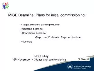
Goals for Running in 2009 • Begin MICE Step I • Commission new target • Commission detectors • GVA1, CKOVa, CKOVb, TOF0, TOF1, FNAL Beam Profile Monitors, KL • High intensity running for study of ISIS activation • Commission Decay Solenoid • Calibrate TOF system • Calibrate CKOV and KL • Perform Beam Studies: • Beam loss vs. Particle Rate • Optimize Upstream Beamline (Q1, Q2, Q3) • Decay Solenoid optimization • Optimize DAQ for increased particle rate • Measure muon beam emittance Linda R. Coney – 16 Jan 2010 4
Outline • Overview of MICE beam line • 2009 Run Goals • Target • Operation • Stability • Detector Commissioning • p, e, p, and m beams • Beam optics optimization and measurements • Upstream Quadrupoles • Decay Solenoid • Muon beam emittance measurements • Conclusions Linda R. Coney – 16 Jan 2010 5
Target Operations • 50,000 pulses of redesigned target in test stand in R78 • New target installed in ISIS August 2009 • Run at base rate (50 Hz/32) and with ISIS at 50 Hz (Normal User Run) • Inspected after 12k, 22k, 42k, 63k – PASSED • Target is working beautifully – NO problems • Target stability checked every 5000 pulses • Process to monitor target behavior agreed upon with ISIS • Target timing wrt ISIS MS signal monitored • Coordinating Beam Loss measured by MICE with that measured by ISIS • Target Operation: 112,000 pulses to date • Machine Physics – 8 days of MICE running • September User Run – 10 days • Nov/Dec User Run – 12 days MICE target path ISIS cycles MS marker ISIS losses Linda R. Coney – 16 Jan 2010 6
Target Monitoring • Target stability checked every 5000 pulses • Study Beam Center Distance (BCD) to monitor target stability • Clear difference between BCD distribution for functioning target and failing target • Failing target has much broader spread • T2 distribution 3-4 times as broad • Interpreted as target “sticking” • Target BCD very stable Linda R. Coney – 16 Jan 2010 7
Target Data Taking • Target Operation Studies: • Search for ideal timing with respect to ISIS cycle • Also a function of target depth • ISIS Beam loss vs particle rate study • Increase target depth, producing ISIS beam loss of 0.1, 0.2, 0.3, 0.4, 0.5, 1, 2, 3 and 4 V • In 2008, maximum ISIS beam loss 50 mV • Found edge of beam at injection g need to avoid next pulse on out-swing • Studies of different accelerations: modified drive voltages on capacitor bank • ISIS machine study: beam bump at MICE target Normal BLMs around ISIS with MICE target inactive (Sector 7) Target operating at 2V beamloss Linda R. Coney – 16 Jan 2010 8
Target Operations • Beamloss (in Sector 7) for the 13 hour run at 1V • Two distinct peaks (although only fitted a single Gaussian) • Double structure due to ISIS beam wandering in cyclic pattern • Not due to variation in target depth! Beam Loss Variation Activation Study • Survey of target area after long 1V run • Slight activation (max. 500 mSieverts/hour) in couple of spots near target • No impact on measurements around the rest of ISIS • ISIS suggests repeat at 5V beamloss Linda R. Coney – 16 Jan 2010 9
ISIS Beam Bump Study • BEAM BUMP TEST (last 2ms of cycle): D. Adams & M. Popovic • 1ms-long kick generated to change nominal orbit • New orbit kept stable for another 1ms • All brought back to the nominal trajectory • The test was performed as follows: 0- use nominal trajectory setting (ISIS) 1- set target BCD for 50 mV losses 2- align target dip minimum with the extraction edge 3- record dip depth and delay 4- extract target 5- introduce the bumped orbit 6- insert target until produce 50mV loss again 7- record dip depth and delay • Results • Ddepth of ~5mm reproduced the 50mV loss (predicted value was 7mm) • ISIS beam closer to target reduces depth needed to generate a defined beamloss g faster insertion, better control of next pulse clipping • Bumped orbit well controlled locally • Rest of orbit very stable Linda R. Coney – 16 Jan 2010 10
Beam Loss vs Particle Rate Study • Beamline set for 300 MeV/c p- beam • Losses calculated using fit to curve of BLM7SUM peak • Error bars (tiny) just from rms/sqrt(#counts) Counts in GVA1 A. Dobbs Linda R. Coney – 16 Jan 2010 11
Beam Loss vs Particle Rate Study II • Beamline set for 300 MeV/c p- beam • Losses calculated using fit to curve of BLM7SUM loss peak • Error bars (tiny) just from rms/sqrt(#counts) Counts in FNAL BPM1 A. Dobbs Linda R. Coney – 16 Jan 2010 12
Next: Beam Loss vs Particle Rate • Repeat analysis using integrated beam loss rather than fit to peak method • ISIS determines MICE losses using integration over full cycle • Rate vs beam loss plots as function of particle type • Uses TOF for PID and rate counter • Cannot use BPMs for this as beam content may change between them • Can use current data for this study • Repeat study with positive particles • Repeat study with muon beamline • Take more data points at higher beam loss Linda R. Coney – 16 Jan 2010 13
Outline • Overview of MICE beam line • 2009 Run Goals • Target • Operation • Stability • Detector Commissioning • p, e, p, and m beams • Beam optics optimization and measurements • Upstream Quadrupoles • Decay Solenoid • Muon beam emittance measurements • Conclusions Linda R. Coney – 16 Jan 2010 14
MICE Beamline and Detectors Linda R. Coney – 16 Jan 2010 15
0.48 m 0.48 m 10 x 4cm scintillator bars sx = 1.15 cm st = 50 ps 7 x 6cm scintillator bars sx = 1.73 cm st = 50 ps Tof-0 Tof-1 Time of Flight Counters • TOF0, TOF1 installed for September & Nov/Dec User Runs • TOF2 installed in late November • Horizontal and vertical bars • Have proven to be invaluable in beamline commissioning Linda R. Coney – 16 Jan 2010 16
Data Taking Program: Positive Particles • Detector Calibration: • 300 MeV/c pions - 4000 target pulses (translates to about 330,000 particles used for calibrating the TOF system) • 250 MeV/c pions - 350 target pulses (also for TOF) • 200 MeV/c pions - 450 pulses (also for TOF) • 300 MeV/c positrons - 1500 target pulses (CKOV and KL calorimeter) • 150 MeV/c positrons - 1200 target pulses (CKOV and KL calorimeter) • Beam Studies: • 330 MeV/c pions to study Decay Solenoid effects on beam optics - 2000 pulses • Muon Beams: • 444 MeV/c pi+ to mu+ beam- 500 pulses Linda R. Coney – 16 Jan 2010 17
333 MeV/c pion beam • Sept 10 with 500mV losses Linda R. Coney – 16 Jan 2010 18
333 MeV/c proton beam • Sept 06 Linda R. Coney – 16 Jan 2010 19
444 MeV/c pi+ to mu+ beam • Motivation to switch beam polarity Linda R. Coney – 16 Jan 2010 20
444 MeV/c pi- to mu- beam • After switched to negative beam Linda R. Coney – 16 Jan 2010 21
Data Taking Program:Negative Particles • In October – switched beamline polarity • Detector Calibration: • 300 MeV/c p- - 2800 target pulses (TOF system) • 300 MeV/c electrons - 5750 target pulses (TOF, CKOV and KL calorimeter) • 150 MeV/c electrons - 1200 target pulses (TOF, CKOV and KL calorimeter) • Beamline Studies: • 300 MeV/c p- for particle rate vs beam loss study – 400 pulses • 300 MeV/c p- for spill gate vs particle rate study – 500 pulses • 330 MeV/c p- for particle rate vs beam loss study – 2400 pulses • 50mV, 100mV, 200mV, 300mV, 400 mV, 500 mV losses • Optimization of Upstream Beamline - 330 MeV/c p- Q1,Q2,Q3 scans – 1100 pulses • Muon Beams – Emittance Measurements • 444 MeV/c p- to 250 MeV/c m- beam - 1500 • 337 MeV/c p- to 250 MeV/c m- beam – 1550 • 444, 420, 400, 360, 337 MeV/c p- to 250 MeV/c m- beam – 500 pulses Linda R. Coney – 16 Jan 2010 22
Data Taking Program with TOF2 • End of November – TOF1 moved, TOF2 installed • Detector Calibration with TOF1 trigger: • 300 MeV/c p- : 6500 target pulses (calibrating TOF system & target delay study) • 250 MeV/c p- : -500 target pulses (TOF system) • 300 MeV/c electrons - 3000 target pulses (TOF,CKOV and KL) • Muon Beams - Emittance measurement data • 444 MeV/c p- to 250 MeV/c m- beam - 9100 pulses • 337 MeV/c p- to 250 MeV/c m- beam – 1000 pulses • 444 MeV/c p- to 200 MeV/c m- beam – 1000 pulses • 444 MeV/c p- to 300 MeV/c m- beam – 1000 pulses • 400 MeV/c p- to 225 MeV/c m- beam – 2000 pulses • 337 MeV/c p- to 200 MeV/c m- beam – 2600 pulses Linda R. Coney – 16 Jan 2010 23
TOF Calibration • Many TOF bars to calibrate • Need lots of data! • Last year’s data……..This year… • TOF system with TOF2 in progress 2009 330 MeV/c (Peaks overlap) p 2008 m 2009 300 MeV/c increased statisticsg e Linda R. Coney – 16 Jan 2010 24
TOF Calibration: Time Resolution • Different calibration done for September and Nov/Dec Runs • Discrimination threshold changed and improved time resolution • September: TOF0 – 52 ps, TOF1 – 68 ps • Nov/Dec: TOF0 – 51 ps, TOF1 – 58 ps • TOF1 completely calibrated, TOF0 all but slab0 and slab9 in both planes Linda R. Coney – 16 Jan 2010 25
Cherenkovs • Two aerogel Cherenkov counters • Installed downstream of Q6 and TOF0 • Used to separate e/m/p 220-350 MeV/c • e/m/p calibration data taken • Sample electron data shown Linda R. Coney – 16 Jan 2010 26
e/m Identifier • KL lead/scintillating fiber calorimeter module • Installed on temporary support with TOF1 in September • Moved downstream and mounted with TOF2 in November • Calibration in progress • Electron data taken • FADCs all working • DAQ restructured & ok • Electron Muon Ranger (EMR) • Triangular prismatic scintillator bars • Being constructed at UGeneva • Installation later this year Linda R. Coney – 16 Jan 2010 27
Outline • Overview of MICE beam line • 2009 Run Goals • Target • Operation • Stability • Detector Commissioning • p, e, p, and m beams • Beam optics optimization and measurements • Upstream Quadrupoles • Decay Solenoid • Muon beam emittance measurements • Conclusions Linda R. Coney – 16 Jan 2010 28
Upstream Beamline Linda R. Coney – 16 Jan 2010 29
data MC nominal config. Optimization of Upstream Beamline: Q1,Q2,Q3 scan • Q1-2-3 varied from nominal value • Charged particles counted downstream of Decay Solenoid • Compared to MC • Charged • p-, m-,e- • Use MC to predict effect for single current changes • verify in the next run Linda R. Coney – 16 Jan 2010 30 14
Optimization of Upstream Beamline: Q1,Q2,Q3 scan • Q1 scan • Good agreement between data and MC for variation of only Q1 1.4 1.2 1.0 0.8 0.6 0.4 0.2 f1-only (MC) DATA Linda R. Coney – 16 Jan 2010 31 0.6 0.8 1.0 1.2 1.4 1.6 1.8
Optimization of Upstream Beamline: Q1,Q2,Q3 scan f2-only (MC) DATA • Q2 scan • Agreement between data and MC not as good as that for Q1 1.4 1.2 1.0 0.8 0.6 0.4 0.2 Linda R. Coney – 16 Jan 2010 32 32 0.6 0.8 1.0 1.2 1.4 1.6 1.8
Optimization of Upstream Beamline: Q1,Q2,Q3 scan Q3 scan Data not agree with MC Q3 could be more sensitive to small misalignment f3-only (MC) DATA 1.4 1.2 1.0 0.8 0.6 0.4 0.2 Linda R. Coney – 16 Jan 2010 33 33 0.6 0.8 1.0 1.2 1.4 1.6 1.8
Run 1121 DS lower 0.30T • Run 1125 DS up 0.30T • Run 1123 Nominal DS Decay Solenoid Optimization • 330 MeV/c pion beam • DS nominal setting 550 A (3.1T) • Vary +/- 10% and study profile in TOF0 • Check data vs MC (our understanding of BL) TOF0 g TOF1 g Study still in progress Linda R. Coney – 16 Jan 2010 34
Extra! Extra! m- m- m- m- m- m- m- m- m- m- m- m- m- m- m- m- m- m- m- m- m- m- m- m- m- m- m- m- m- Muon Beam Studies at MICE! Extra! Extra! • The MICE experiment takes 17000 target pulses of muon beam data! • ~170,000 m at TOF1 • Muon beam e studies begin! Blimey! Muons! Worldwide celebrations ensue! Locals in Britain express strong support for the experiment Linda R. Coney – 16 Jan 2010 35
Muon Beam Data • Muon Beams - Emittance measurement data • 444 MeV/c p- to 250 MeV/c m- beam - 10,600 pulses • 337 MeV/c p- to 250 MeV/c m- beam – 2500 pulses • 444 MeV/c p- to 200 MeV/c m- beam – 1000 pulses • 444 MeV/c p- to 300 MeV/c m- beam – 1000 pulses • 400 MeV/c p- to 225 MeV/c m- beam – 2000 pulses • 337 MeV/c p- to 200 MeV/c m- beam – 2600 pulses • Preliminary muon rate survey • 337 MeV/c p- to 250 MeV/c m- beam • Varied target depth to study muon rate as function of beam loss • VERY preliminary! Linda R. Coney – 16 Jan 2010 36
Initial 4D eN (mm) 3 6 10 Absorber Pz (MeV/c) 140 Data 200 240 D1 D2 Cooling channel and spectrometers Q1 Q2 Q3 Q4 Q5 Q6 Q7 Q8 Q9 DK sol Target TOF0 TOF1 Diffuser Muon Beam Emittance Measurements • Purpose: generate the elements of the “emittance-momentum matrix” • Study performance at every portion of a full cooling channel • Can we use the TOFs to demonstrate the matrix elements? MICE note 176 Apollonio, Cobb M. Rayner Linda R. Coney – 16 Jan 2010 37
dnstream BL tuning: match to diffuser m Q1 Q2 Q3 Q4 Q5 Q6 Q7 Q8 Q9 Dipole1 Dipole2 DK solenoid p fix D2 fix D1 Pp=444 MeV/c Pm=255 MeV/c Pm=214 MeV/c Pm=208 MeV/c 38 Marco Apollonio - Imperial College
Measuring (e,P) from DATA • Rationale • check if an optics produces the foreseen (a,b) at diffuser • measure e (and P) of the muon beam • measure beam spread (sigx) and divergence (sigx’ = sig(px/pz)) • How? • use TOF0 / 1 as (x,y) stations • define muon sample • track mu’s in the Q7-8-9 triplet • infer x’, y’ (x,x’) (y,y’) • scatter plots give phase spaces Mark Rayner’s tools Linda R. Coney – 16 Jan 2010 39
Muon Beam e Measurement • Use PID on December’s scaled pm decay beam line data • Define muon sample “Central” beamline optics 444 MeV/c pg 250 MeV/c m at D2 6-200 Runs 1380-1397 and 1391-1393 Intermediate momentum beam line with scaled quad currents Runs 1407-1408 444 MeV/c pg 225 MeV/c m at D2 6-140 (rescaled currents) Runs 1409-1411 337 MeV/c pg 200 MeV/c m at D2 Linda R. Coney – 16 Jan 2010 40 M. Rayner
Reconstruction procedure • Iterative calculation of increasingly good s=Dz+d and P • Begin with P from P/E=Dz/t • 1 Calculate a linear transfer map at P from TOF0 to TOF1 (top hat quadrupoles) • 2 Deduce x0’ and y0’ from x1 and y1 • 3 Integrate ds while tracking the initial trace space vector through the beam line • 4 Make a better estimate of P from P/E=s/t • 5 Make a small Bethe-Bloch correction for the energy loss in air between the TOFs Linda R. Coney – 16 Jan 2010 M. Rayner Marco’s=6mm pabsorber=200 MeV/c centre of the e-p matrix beam 41
Truth Muon Beam e Measurement:x and y trace space Recon’d det. sim. Data M. Rayner Linda R. Coney – 16 Jan 2010 42
Goals for Running in 2009 Revisited • Begin MICE Step I • Commission new target • Commission detectors • GVA1, CKOVa, CKOVb, TOF0, TOF1, FNAL Beam Profile Monitors, KL • High intensity running for study of ISIS activation • Commission Decay Solenoid • Perform Studies: • Decay Solenoid optimization - in progress • Beam loss vs. Particle Rate - in progress • Optimize Upstream Beamline (Q1, Q2, Q3) • Calibrate TOF system • Calibrate CKOV and KL ongoing • Optimize DAQ for increased particle rate ongoing • Measure muon beam emittance – started – ongoing Linda R. Coney – 16 Jan 2010 43
m Conclusions • Beamline is working! – negative or positive particles • New target operating smoothly - Systematic monitoring of performance • Decay Solenoid routinely operated – factor 5 increase muon rate • Major increase in loss limits 50 mV (2008) g 1V (2009) • DAQ increase in efficiency: <50 particles/spill (2008) g ≤ 200 part/spill (2009) • Beam loss vs particle rate shows linear dependence • Detectors are working! • TOF0, TOF1 calibrated – TOF2 next • Need more data for TOF2, KL • EMR installation – Summer2010 • Muon beam optics physics is happening! • Upstream beamline is tuned • Initial measurement of muon beam emittance • Muon Rate Study – in progress • More (e,P) matrix data in February/March Linda R. Coney – 16 Jan 2010 44
Target Operations • Beamloss (in Sector 7) for the 13 hour run at 1V • Two distinct peaks (although only fitted a single Gaussian) • Double structure due to ISIS beam wandering in cyclic pattern • Not due to variation in target depth! Beam Loss Variation Activation Study • Survey of target area after long 1V run • Slight activation (max. 500 mSieverts/hour) in couple of spots near target • ISIS suggests repeat at 5V beamloss Linda R. Coney – 16 Jan 2010 9
Target Operations II • Target I stability from 16 Sept 2009 • Characteristic double peak due to inherent 0.15 mm position resolution and the pulse by pulse capture position • deltaD for 5th = .13 and for 16th = .12 • Running at same depth – consistent behavior Linda R. Coney – 16 Jan 2010 6
Decay Solenoid • Operation of Decay Solenoid is now routine • Provides gain of ~5 in particle flux Without DS With DS Linda R. Coney – 16 Jan 2010 34
Decay Solenoid • Operation of Decay Solenoid is now routine • Provides gain of ~5 in particle flux Without DS With DS Linda R. Coney – 16 Jan 2010 35
Beam Stop Open! • Remote operation of Beam Stop Linda R. Coney – 16 Jan 2010