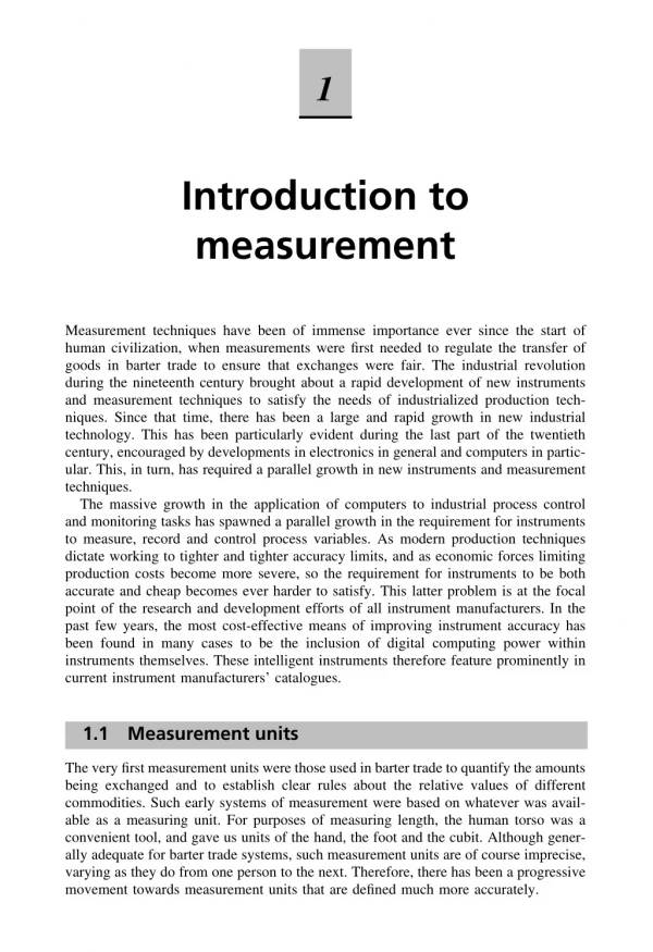
Download

1 / 16
160 likes | 189 Views
MECH 373 Instrumentation and Measurements. Lecture 18. Measurement of Solid-Mechanical Quantities (Chapter 8). • Measuring Strain • Measuring Displacement • Measuring Linear Velocity. • Measuring Accepleration and Vibaration • Measuring Force. Measurement Systems.

E N D
MECH 373Instrumentation and Measurements Lecture 18 Measurement of Solid-Mechanical Quantities (Chapter 8) • Measuring Strain • Measuring Displacement • Measuring Linear Velocity • Measuring Accepleration and Vibaration • Measuring Force
Measuring Strain (Strain Gages) • • What is Strain? • Deformation of a body due to an applied force. • Fractional change in length, e.g., blade subjected to CF forces. • • Sensor used - strain gauges. • • Typical Electrical Resistance Strain Gage (resistance strain gauge) • • Ideal sensor has following: • - Good spatial resolution, implying sensor - measure strain at a point. • - Unaffected by changes in ambient conditions. • -High-frequency response for dynamic strain measurements.
What is Strain Gage? A strain gauge - Electrical resistance proportion to strain in the device - bonded metallic strain gage.
Measuring Strain (Strain Gages) • Electrical resistance strain gage – also as sensing element (transducers), e.g. measure force, acceleration and pressure. • Electrical-resistance strain gages and associated signal conditioners - simple, inexpensive and quite reliable. • Function of a strain gauge as shown below:
Measuring Strain (Strain Gages) • Supported beam bent by applied lateral force. • Beam longer on the bottom surface and shorter on the top surface. • A wire that is attached to the beam. • Consider the original length of the wire be l (i.e. under no loading). • When the beam is loaded, wire stretched and its length becomes l + δl. • Ratio δl/l - strain - given symbol ε. • Strain in wire is approximately the same as the strain in lower beam surface • Wire stretching cause its electrical resistance to change.
Measuring Strain (Strain Gages) • • Strain units - inches per inch or millimeters per millimeter dimensionless. • Strain in structures very small, e.g., low-strength steel yield at 0.0014 strain (0.14%). • • Expressed in units of microstrain (μstrain), 0.0014 strain = 1400 μstrain. • • Determine the stresses in structure to check the structure integrity. • • To measure the stress directly - No, but strain –Yes. • But stress (Hooke’s law): • σ = Eε • where, σ = Normal stress , E = Modulus of elasticity (material property). • • For wire = strain gauge, the relationship between the change in resistance and the strain must be known.
Measuring Strain (Strain Gages) • • The resistance of a wire is given by • where, R is the resistance, ρ is the resistivity of wire which is a function of the wire material, L is the length of wire, and A is the cross-sectional area of the wire. • • Taking logarithms of both sides: • • Assumption: Small change in resistance to changes in resistivity, length and cross-sectional area. • • The term dL/L is the axial strain, εa. • • The term dA/A can be evaluated from the equation of the cross-sectional area A=πD^2/4. • • Taking the logarithm and differentiating the above equation we get
Measuring Strain (Strain Gages) • • Term dD/D = transverse strain, εt. • • Relationship between the axial and transverse strain • where, v is known as Poisson’s ratio and it is the property of material. • • Combining the above equations we get • Above equation shows relationship between the change in resistance of the wire, strain, and the change in resistivity of the wire. • • The strain gage factor, S, is defined as • • Combining the above two equations we get
Measuring Strain (Strain Gages) • If the temperature is held constant, the change in resistivity is proportional to the strain. • The strain gage factor is approximately constant, although it is sensitive to the temperature change. • In summary, we have following equations:
Measuring Strain (Strain Gages) • Strain gages construction - straight wires, etching them from thin foil metal sheets - bounded to a plastic backing, as shown below. • Backing glued to the structure to measure strain. • Dimensions of strain gages as small as 0.2mm, Common 2 to 3mm. • Strains as high as 200,000 με can be measured. • Strain gages constructed - semiconductor materials. • Commonly used as sensing elements in pressure and acceleration transducers - cannot measure very high strain.
Measuring Strain (Strain Gages) • Transverse strain: • This strain can be measured as: This effect is included when manufacturers determine strain gage factors. • Normally, structure stressed simultaneously in more than one direction, leading to the so-called biaxial stress. • In biaxial stress - transverse strain that results from the transverse stress. • This transverse strain affects the strain gage output and be described with a transverse gage factor, St, defined as • The transverse sensitivity effects are usually neglected in the strain measurements. • To define the strain on a surface, it is necessary to specify two orthogonal linear strains εxand εy, and a third strain called the shear strain, γxy, the change in angle between two originally orthogonal lines when the solid is strained. • These strains can be determined by three suitably placed strain gages in an arrangement called a strain rosette.
Measuring Strain (Strain Gages) • • Two common arrangements of the three strain gages are: • - Rectangular rosette • - Equiangular rosette • • In rectangular rosette, the gages are placed at angles of 0, 45 and 90 degrees. • • In equiangular rosette, the gages are arranged at 0, 60 and 120 degrees.
Measuring Displacement • Potentiometers are very common devices used to measure displacement. A linear potentiometer is used for linear measurements and an angular potentiometer is used for angular measurements. • The linear potentiometer is a device in which the resistance varies as a function of the position of a slider, shown below. • With the supply voltage (Vs), the output voltage (Vo) will vary between zero and the supply voltage. • For linear potentiometer, the output is a simple linear function of the slider position. That is
Measuring Displacement • It should be noted that the device measuring Vo must have a high impedance to maintain a linear response and avoid loading error. • Linear potentiometers can be used to measure displacements as small as 0.1 to 0.2 in. (2.5 to 5 mm) up to displacements of more than 1 ft.