Download
1 / 63
660 likes | 929 Views
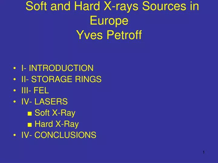
Soft and Hard X-rays Sources in Europe Yves Petroff. I- INTRODUCTION II- STORAGE RINGS III- FEL IV- LASERS ■ Soft X-Ray ■ Hard X-Ray IV- CONCLUSIONS. I-INTRODUCTION.

E N D
Soft and Hard X-rays Sources in Europe Yves Petroff • I- INTRODUCTION • II- STORAGE RINGS • III- FEL • IV- LASERS ■ Soft X-Ray ■ Hard X-Ray • IV- CONCLUSIONS
I-INTRODUCTION • During the last few years, I have been involved with ESFRI ( European Forum for Research Infrastructures): we have produced last year a Road Map (~DOE) but including biomedical and life sciences, Social Sciences & Humanities. • There are 35 projects on the list: each project is receiving ~5 M€ (from the European Commission) for the next 2 years. • For construction, most of the money has to come from the countries
ESFRI ROAD MAP → → → → → NETWORKS POSSIBLE IN SSH, BIOMED. LIFE SCIENCES
Soft and Hard X-Ray projects • Upgrade of the ESRF: 230 M€ • Integrated Str. Biology Infrastructure: 300 M€ • XFEL (Desy): 986 M€ • IRUVX-FEL Network: Flash (Desy), Bessy (Berlin), MAX IV (Lund), 4 GLS (UK), Fermi (Trieste): 760 M€ • ELI (Laser ≥ 100 PW): 150 M€
II- STORAGE RINGS • Existing • Under discussion
BL in Europe on existing or under construction S.R E (GeV) I (mA) H (nmrad) BL in oper. Stations BL in constr. PX • ISA 0. 58 200 7 1 • SOLEIL 2. 75 300/500 3. 7 13 12 (2012) 1+1 • ESRF 6. 00 200 3/4 38 46 10.5 • ANKA 2. 50 150 50 12 3 • BESSY 1. 70 300 5 28 34 3 • DORIS* 4. 45 140 410 34 6 • PETRA* III 6.00 100/200 1 14 (2009) 4 • ELETTRA 2 (2.4) 330/150 7/9.7 18 26 1 • ALBA* 3 400 4.3 7 (2010) 1 • MAX -MAX I 0. 55 300 40 5 -MAX II 1. 5 200 8.8 11 5 -MAX III 0. 7 200 13 3 • SLS 2. 4 400 5 13 4 3 • SRS* 2. 00 150/250 12 1 • DIAMOND 3. 00 150/300 2.74 9 13 (2012) 3+2 • TOTAL203 223 54 41.5 SRS will end in 2008, DORIS? The number of BL will not increase
Projects of SR facilities in Europe • Poland (Cracovia) • Tchequia (Brno), 3 GeV, decision in Jan. 2008 • Sweden (MAX IV) New location: 2 SR at 3 and 1.5 GeV with a 3 GeV linac + moving MAX III + a soft X-Ray FEL • ESRF upgrade
ESRF upgrade • The focus wil be mostly on BL and detectors • For the accelerator - increasing the length of selected ID straight sections - canting selected straight sections - increasing the current from 200→300 mA - decreasing the vertical emittance operating in top up mode for time-strucured modes - improved beam position diagnostics - brilliance: 5. 1020 ph/s/0.1%/mm2/mr2
ESRF UPGRADE: Main Features • Upgrade of the Accelerator Complex: • Increased brightness, stability, reliability, and operation • flexibility. • 2. New, refurbished and upgraded Beamlines Portfolio: • Improved performance and routine nano-focus beams. • 3. Extension of ~1/2 of the Experimental Hall : • Long beamlines enabling nano-meter and nano-radian beams. • 4. Development of new SR Instrumentation: • Underpin beamlines and source improvements. • 5. New Infrastructure Enabling Science-driven Partnerships: • New science and applications with increased participation • of Academia, Research Labs, Industry, …. .
ESRF-2000/2006: shifts requested/accepted and User visits Shifts scheduled User Visits
Why the number of users is increasing? I- Qualities of the sources and the experiments • Emittance: 3/7 nm.rad with a coupling < 1% • Brilliance: 1019-1021ph/s/mm2/mrad2/0.1% bw • Fiability: 98% • Stability • Machines mostly based on undulators (due to the possibilty to tune simultaneously the undulator and the monochromator) • Top up - necessary for low energy rings - for high energy rings: it is depending of the experiments • Flexibilty: single or few bunches, hybrid….but > 50 ps • Purity in the bunch: 10-10 • Polarization II- New fields: paleontology, archeology…… III- Massive automation in structural biology
Archaeopteryx is the earliest known bird ? • Discovered in Germany in 1861. • Missing link between birds and dinosaurs. • Crow-sized, lived about 150 M yrs. • Feathers identical to that of modern bird. • Also had sharp teeth, a long bony tail, • clawed fingers, and long feathers on its • back and legs. • ► This suggests that the first birds were • four-winged gliders that coasted • between treetops like flying squirrels.
Cretaceous enigmatic tiny egg from Thailand P. Tafforeau, E. Buffetaut Dinosaur or Bird ?
Available crystals become smaller • InterAvailable crystals become smaller • Interesting complexes become larger • 2006 figures ( >160.000 samples tested) expected to increase by more than a factor of 10 • esting complexes become larger • 2006 figures ( >160.000 samples tested) expected to increase by more than a factor of 10 • ble crystals become smaller • Interesting complexes become larger • 2006 figures ( >160.000 samples tested) expected to increase by more than a factor of 10 Structural/functional Biology and Soft Matter • Available crystals become smaller • Interesting complexes become larger • 2006 figures (> 160000 samples tested) expected to increase by more than a factor 10 Massive Automation and Nano-beams Needed F Brueckner et al. Science , 315, 859-862, 2007
Conclusions on SR • It is important to scale down, as much as possible, the construction and the running costs. • People focus to much on the machine, not enough on the experiments. • SR run for 30 years or more: however, after 5/6 years parts of the beamlines are obsolete: it is important to iclude money for refurbishment. • The most imortant parameter is the quality of the staff at the BL.
III-FEL in EUROPE • IR - CLIO (ORSAY), RF linac FEL, E=15/50 MeV, 3-150 μm, 5 exp., in operation since more than 15 years - FELIX (RIJNHUIZEN) RF linacs, E1=15/25 and E2=25/45 MeV, 4-250 μm, 10 exp., in operation since 15 years - FELBE (DRESDEN), superc. cw linac, E=12/34 MeV, 3-200 μm, in operation, 6 exp, coupled with the Magnetic High-Field Lab. - ENEA (Frascati), microtron, E=2/5.5 MeV, 2.5 mm-200 μm • VUV-Soft X-Ray - FLASH (Hambourg): in operation,superc. linac, E=1 GeV, 6 nm, 10 fs,1 KHz, 5 exp. - FERMI (Trieste): under construction, RF linac, E=1.2 GeV, 10 nm, 1.4 ps, 50 Hz - BESSY (Berlin): no decision but R&D, superc.linac, E= 2.3 GeV,1.24 nm, 30 fs,1 KHz, 10 exp. - 4 GLS (Daresbury): no decision but R&D (ERLP, 35 MeV), superc. linac, ERL+FEL, 10 nm, 50 fs - MAX IV (Lund): no decision, 3 GeV linac • Hard X-Ray - XFEL (Hambourg): under construction, superc. linac, E=17.5 GeV,≤ 0.1 nm, 80 fs, 1 KHz, 6 exp?
- FLASH (Hambourg): in operation,superc. linac, E=1 GeV, 6 nm, 10 fs,1 KHz, 5 exp.
Currently there are four beamlines (PG2, BL1, BL2, BL3) in operation and a fifth beamline (PG1) is under construction. An additional optical laser system is provided for pump-probe experiments. It is fully synchronized with the FEL beam. FLASH
FERMI (Trieste): under construction, RF linac, E=1.2 GeV, 10 nm, 1.4 ps, 50 Hz
BESSY (Berlin): no decision but R&D, superc.linac, E= 2.3 GeV,1.24 nm, 30 fs,1 KHz, 10 exp.
BESSY FEL • In October 2006 BESSY has finalised the proposal for the proof of principle facility STARS (Superconducting Test Accelerator for Radiation by Seeding). As recommended by the science council STARS will demonstrate the principle of cascading HGHG stages – the fundamental for the BESSY FEL. • On November 12th 2007, the first superconducting electron gun was put in operation at the Forschungszentrum Dresden-Rossendorf. Running a FEL by a superconducting gun allows to generate laser pulses in a continuous wave mode. • First CW operation of a fully dressed TESLA cavity at 20 MV/m. TESLA Cavities are the heart of Linacs in virtually all FEL projects. These cavities were originally developed by DESY and Cornell to drive Linacs for particle physics and hence to be operated in pulsed mode. When driving an FEL for a user facility to produce ultrashort X-ray pulses however, it is of major importance to increase the pulse rate to a continuous wave (CW) mode with up to 20 kHz. This can be achieved by using superconducting niobium cavities operated at 2 K. However, the heat production due to remaining gas in the vacuum tube or minor inaccuracies in the cavities can exceed a level to make it impossible to keep the temperature as low as 2 K. Hence, special care has to be taken in the quality of the cavity. Ultra-clean assembly of all the cavity components thus is vital. Other options to reduce the losses include lowering the operating temperature from 2.0 K to 1.8 K.BESSY designed the HoBiCaT Test Facility to study CW operation of TESLA cavities. Recent tests, in collaboration with DESY and Jefferson Lab, of a fully dressed TESLA cavity (input coupler, liquid helium tank, HOM couplers, tuner) have demonstrated that CW operation up to 20 MV/m
4 GLS (Daresbury): no decision but R&D (ERLP, 35 MeV), superc. linac, ERL+FEL, 10 nm, 50 fs
IV- LASERS • The SR community has been contaminated by the High Energy Physics virus: bigger and bigger, more and more expensive machines. Ex: XFEL (Desy): 3.4 Km, could be shorter! This postponed the project for 4 years • Everybody is focusing to day on FEL • 1013 ph/pulse at few Hz or 108 at 100KHz? For solid state physics, the second is more important • Problems - cost - size - pump-probe experiments? • It is good to look in different directions
Ultrafast Control of the Electronic Phase of a Manganite via Mode-Selective Vibrational ExcitationM. Rini, R.I. Tobey, N. Dean, Y. Tomioka, Y. Tokura, R. W. Schoenlein & A. Cavalleri,(Nature, accepted) • Controlling a phase of matter by coherently manipulating specific vibrational modes has long been an attractive and yet elusive goal for ultrafast science.Solids with strongly correlated electrons, in which even subtle crystallographic distortions can result in colossal changes of the electronic and magnetic properties, can indeed be directed between competing ground states by selective modulation of infrared active vibrations. • Rini et al.,report on the ultrafast switching of the electronic phase of a magnetoresistive manganite via direct excitation of a phonon mode at 17-THz. A prompt, five-order-of-magnitude drop in resistivity is observed, associated with a non-equilibrium transition from the stable insulating phase to a metastable metallic phase. • In contrast with light-induced and current-driven phase transitions, the vibrationally-driven bandgap collapse observed here is not related to hot-carrier injection and is uniquely attributed to a large-amplitude Mn-O distortion. This corresponds to a perturbation of the perovskite-structure tolerance factor, which controls the electronic bandwidth via inter-site orbital overlap. • Phase control by coherent manipulation of selected metal-oxygen phonons will find extensive application in other complex solids, notably in the cuprate superconductors in which the role of Cu-O vibrations on the electronic properties is controversial.
Pr0.7Ca0.3MnO3 ↑ ↑ ↑ Mn-O stretching Mn-O-Mn bending
Very fast progress in two areas in the last few years • High-order harmonic upconversion of femtosecond lasers produces a source of short-wavelength (coherent) light with femtosecond-to attosecond pulse duration. Recently, phase matching has been introduced by various groups: RAL (PRL, 99,143901, 2007), Boulder (Nature Physics 3, 271, 2007)→4nm (10 nJ). Every 3 months there is something new!! • B. Dromey et al. (Nature Physics 2, 456, 2006) present the first experimental demonstration of high harmonic generation (n ≥ 850) in the relativistic limit, obtained on the Vulcan Petawatt laser. High conversion efficiencies (>10-6 per harmonic) and bright emission (>1022 ph/s/mm2/mrad2 /0.1% bw are observed at wavelengths < 4 nm. • Seeded FEL to reduce the size and the cost (G.Lambert et al. Nature Physics: to be published) • Laser-plasma-based accelerators • The SR community can’t ignore these developments in the soft X-Ray region
H.N. Chapman et al. Nature Physics 2, 839, 2006Coherent microscopy: FEL (Hambourg), 32 nm Single pulse
R. L. Sanberg et al. P.R.L 99, 098103, 2007Table top laser: 29nm Not a single pulse but could have been done also with one pulse because the same group has made a laser at 32.6 nm with 2.1026 ph/s/mm2/mrad2/0.01%bw.
Bright Quasi-Phase-MatchedSoft-X-Ray Harmonic Radiation from Argon IonsM. Zepf, B. Dromey,M. Landreman, P. Foster, and S. M. Hooker PRL 99, 143901, 2007 >1010 per harmonic peak /s (10 Hz system) and a peak brightness of >1021 ph/s/mm2/mrad2/ 0.1% bw, Conversion eff. ≥ 10-6 at 300 eV: 10 nJ!!
G. LAMBERT, T. HARA, D. GARZELLA, T. TANIKAWA, M. LABAT, B. CARRE, H. KITAMURA, T. SHINTAKE, M. BOUGEARD, S. INOUMERDJI, O. CHUBAR, O.GOBERT, K. TAHARA AND M. E. COUPRIE, Saclay- Riken- Soleil (to be published in Nature Physics) • They demonstrate, with a 150 MeV linac, the strong amplification at 160 nm of an ideal soft X-ray seed source, the High-order Harmonics Generation in gases (HHG), and the generation of Non Linear Harmonics (NLH) at 54 nm and 32 nm, within a first 4.5 m long undulator of the SCSS test accelerator. Indeed, the 160 nm seeded emission achieves three orders of magnitude higher intensity than the unseeded one. Moreover, the FEL saturation length is twice smaller.
In a FEL, a high quality relativistic electron beam propagates through an undulator. The horizontally wiggling particles radiate synchrotron radiation -the spontaneous emission (SE)-, which interacts with the electron beam via energy exchange along the undulator. Then, the electron bunch density is modulated in the longitudinal dimension by a period close to the SE wavelength (bunching), so that the different slices start to emit in phase. In SASE, the amplification starting from SE requires long undulators for reaching saturation. Moreover, the bunching takes place independently at different parts of the bunch and limits the longitudinal coherence of the radiation. Hence, seeding a FEL with an external coherent source forces a faster and more efficient bunching of the electrons than in SASE (as shown , few years ago by Yu at Brookhaven). The saturation is then achieved over shorter undulator length, resulting in a more compact source. Since amplification is coherently triggered within the seed pulse length, instead of erratically from SE in the SASE, the pulse temporal/spectral profiles should no longer present statistical fluctuations (spikes). Similarly, seeding should eliminate the temporal jitter, i.e. the random structure of the FEL pulse typically varying in femtosecond range. Furthermore, the FEL spectral gain width, which is inversely proportional to the number of undulator periods, becomes large enough at short wavelengths to match and amplify broadband seed while preserving its coherence properties, so that ultra-short pulses in the femtosecond range can in principle be produced in VUV to X-ray region.
The seed pulse energy was 0.53 nJ and only the first undulator section was used for amplifying the HHG pulse.
-Gaussian shape -No jitter -Stable -Fel satur.length twice smaller -The 160 nm seeded emission is 2600 higher than the unseeded one -The seed pulse energy is only 0.5 nJ !!!
New possibilities • ≤1 GeV FEL+seeding →1nm?, kHz • IR FEL (Jefferson type) +H →1nm?,MHz • Laser plasma based accelerator →1 nm, Hz
Laser-plasma-based accelerators • In a conventional accelerator, e- or protons are accelerated by an alternating, RF electric field through metallic cavities. • The rate of acceleration is limited by the peak power of the RF source and by the electrical breakdown at the metal walls. • Laser-driven plasma waves overcome both of these limitations: the high peak power of lasers is unmatched, and the plasma, an ionized gas, is insensitive to electrical breakdown. • In 1995, Modena et al.(Nature 377, 606, 1995) made clear the remarquable potential of this scheme.
Laser-plasma-based accelerators • In laser-plasma-based accelerators, the longitudinal accelerating electric field is excited via the ponderomotive force of an ultrashort and ultra-intense laser. This force is proportional to the gradient of the laser intensity. • The ponderomotive force pushes electrons outward and separates them from the ions, thus creating a travelling electric field, with a phase velocity vp close to the speed of light in vacuum c, as is required for accelerating particles to relativistic energies. • This wakefield can have a longitudinal electric field Ez > 100 GV m-1 and the characteristic scale length of the accelerating structure is the plasma wavelength λp = 10-30μm, for typical plasma densities of ne = 10181019 cm-3. To be trapped and accelerated, electrons need to be injected into the wakefield with sufficient initial energy.
Laser-plasma-based accelerators • However, for nine years the progress was slow: the number of particles in the beam, their spread in angle and energy were not very good. The energy spread of the beams was 100%. • Injection is difficult because the λ of the plasma wave is 104 times shorter than the usual 10-cm λs of the RF fields in conventional accelerators. That why injecting tightly packed bunches of e- near the plasma-wave peak was expected to be a challenge.
Laser-plasma-based accelerators • However, at the end of 2004, 3 groups in Rutherford1, Berkeley2 and Palaiseau3, reported simultaneously exciting results. • Using 10/30 Tw of laser power, in pulses 30/55 fs long, focused into an ionized jet of gas 2 mm long, they obtained a particle density of 2.1019 cm-3 with a nearly monoenergetic distribution of e- (with instrument-limited energy spreads of 2/24%) at roughly 80/170 MeV. • With up to few 2.109 e-/beam, the energy density was 103 times higher than previously achieved and the angular spread was comparable to the best of the beams produced by RF systems. 1. Mangles, S.P.D. et al. Nature 431, 535, 2004 2. Geddes, C.G.R. et al. Nature 431, 538, 2004 3. Faure, J.et al. Nature, 431, 541, 2004
Laser-plasma-based accelerators:recent important improvements 1- The mechanism responsible for injecting e- into the wakefield is based on hightly nonlinear phenomena, and it is therefore hard to control. Faure et al.(Nature 444, 737, 2006) have recently shown that the injection and subsequent acceleration of e- can be controlled by using a second laser pulse. The collision of the 2 laser pulses provides a pre-acceleration stage which provokes the injection of e- into the wakefield. The results show that the e- beams are: - collimated (< 5 mrad) - monoenergetic (energy spread < 5%) - tuneable between 15/250 MeV - τ < 10 fs - stable 2- Leemans et al.(Nature Physics 2, 696, 2006) have obtained a high quality e- beam with 1 GeV energy by channelling a 40 Tw peak-power laser pulse in a 3.3 cm-long gas filled capillary discharge waveguide.
WHAT IS THE NEXT STEP? • Short Term: ILE (Palaiseau): 10 Pw, under construction,2008/2011, 28 M€ (not the real budget because a large fraction of the personnel, some buildings and equipements are not included) • Long Term: ELI (European Project), in a preparation phase, 150 M€???
GENERAL GOALS OF ILE • To gain one or two orders of magnitude in laser intensity, compared to existing sources. • To create secondary sources of intense short pulses of particules or photons. • To install infrastructures allowing users of various communities to do experiments in safe conditions. • To be a prototype for ELI
ILE There will be five thematics: • sources of electrons and ions • sources of XUV/X laser radiation in a plasma • sources of Hard X –Ray • attosecond sources • the physics of intense fields
Laboratories involved in the project • Laboratoire d’Optique Appliquée (1), • Laboratoire d’Utilisation des Lasers Intenses (2), • Laboratoire Charles Fabry de l’Institut d’Optique Théorique et Appliquée (3), • Laboratoire Louis Leprince-Ringuet – LLR (4), • Centre de Physique Théorique – CPhT (5), • Laboratoire d’Interaction des rayons X Avec la Matière – LIXAM (6), • SPAM du CEA/DSM/DRECAM Saclay (7), • LILM du CEA/DEN Saclay (8), • DMPH et le DOTA de l’Office National d’Etudes et de Recherches Aérospatiales (9), • Laboratoire des Solides Irradiés – LSI (10), • Laboratoire de Physique des Gaz et des Plasmas – LPGP(11), • Laboratoire Optique et Biosciences – LOB (12) • Laboratoire de l'Accélérateur Linéaire d'Orsay- LAL (13).