Download
1 / 22
220 likes | 357 Views
Unlock the world of three-phase systems, pulse width modulation, and inverter-driven applications with this comprehensive training. Discover the advantages of Poly-Phase systems and learn about power calculation methods. Delve into the intricacies of three-phase measurements and understand the basics of Pulse Width Modulation. Explore the principles behind inverter operation, including regeneration of AC signals and motor speed control. Gain practical insights through demonstration circuits and real-world examples. Enhance your knowledge of electrical systems and elevate your expertise in three-phase technologies.

E N D
Three Phase Inverter Motors Ben Kemink
Three Phase Inverter Motor At the end of this training session you will have learned; • There are different three-phase measurements. • Pulse Width Modulation. • Inverter Driven Applications mess-up with Period Time T.
Three Phase Systems A One-Phase System, also called a Single-Phase (SP) System works very much similar to a DC network and can be considered so far at any particular moment in time. Electrical Systems comprising two or more phases are also called Multi-Phase or Poly-Phase (PP) systems. The voltage amplitudes and frequencies in the individual system circuits are the same, but they have definite phase differences.
Why Poly-Phase? The technical complications and economical investments are small compared to the enormous advantages of a Poly-Phase system: 1. Same size generator or motor, higher output. 2. Same energy transmission less copper required. 3. PP motors have uniform torque, SP have pulsating torque *). 4. PP motors are self-starting, SP are not *). 5. Polyphase generators work fine parallel, SP not. *) Single Phase commutator motors are exception.
Three Phase is ideal Source: Advanced Electrical Technology by H.Cotton
Three-Phase Three-Wire Total Power calculation based on Two-Watt-meter method 3 wires – 1 = 2 power meters required
Three-Phase Four-Wire 4 wires - 1 = 3 Watt meters are required
Three-Voltage Three-Current Calculation based on Two-Watt meter method. Third Phase measurements are added.
Introduction • What is Three phase? • Three phase = three signals • Phase shift: 1200 Figure 1: Phase shift 1200
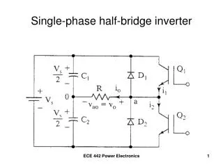
Demonstration circuit Demonstration circuit consists of: • Frequency inverter; • 3-Phase Electromotor; • Power meter; Figure 2: Demonstration circuit
L1(mains) Demonstration circuit • Freq. inverter • Step 1: AC → DC • Step 2: DC → 3-Phase T T Control unit 0 Hz → 50 Hz Figure 3: Block diagram 1phase inverter
Demonstration circuit • AC → DC • Performed by rectifier; • DC-signal is smoothened by capacitor; • In 3phase mains the output of the rectifiers is connected to the same capacitor; • Freq. inverter Step 1: rectifying Example: Single phase rectifying t → Figure 4: rectifier
U t Demonstration circuit • Freq. inverter • Step 2: regeneration of 3-Phase-signals • Six switches • Generate periodic pulse-trains; • Insulated Gate Bipolair Transistor (IGBT); • High frequency switches; New Period T t Figure 5: Inverter step 2: regeneration of AC-signals
Demonstration circuit • Freq. inverter • YEF-HQ Test Motor Figure 6: Output of Freq. Inverter: 1-phase, current (green) / voltage (yellow)
U U V V W W Running the motor CW • Direction • Direction (CCW or CW) • Can be changed by manipulating the pulses CCW
U U V V W W Running the motor T • Speed • Depends on the switching frequency Slow Two times faster T
Faster 1s time window Running the motor • Speed: voltage (yellow) and current (green) • Slow • 1s time window Figure 7: Output of Freq. Inverter at different speeds
Now you have learned; • There are different three-phase measurements. • What Pulse Width Modulation is. • Why Inverters mess-up with Period Time T.