Three Phase Inverter Motors
230 likes | 904 Views
2. At the end of this training session you will have learned;. There are different three-phase measurements.Pulse Width Modulation.Inverter Driven Applications mess-up with Period Time T.. Three Phase Inverter Motor. 3. Three Phase Systems. A One-Phase System, also called a Single-Phase (SP) Syst

Three Phase Inverter Motors
E N D
Presentation Transcript
1. Three Phase Inverter Motors Ben Kemink
2. 2 At the end of this training session you will have learned;
There are different three-phase measurements.
Pulse Width Modulation.
Inverter Driven Applications mess-up with Period Time T.
3. 3 Three Phase Systems
4. 4 Why Poly-Phase?
5. 5 Why 3 Phase and not 7?
6. 6 Three Phase is ideal
7. 7 Three-Phase Three-Wire
8. 8 Three-Phase Four-Wire
9. 9 Three-Voltage Three-Current
10. 10 Three-Phase Three-Wire with PT & CT
11. 11 Introduction What is Three phase?
Three phase = three signals
Phase shift: 1200
12. 12 Pulse Width Modulation of a Sine Wave
13. 13 Demonstration circuit Demonstration circuit consists of:
Frequency inverter;
3-Phase Electromotor;
Power meter;
14. 14 Demonstration circuit Freq. inverter
Step 1: AC ? DC
Step 2: DC ? 3-Phase
15. 15 Demonstration circuit
AC ? DC
Performed by rectifier;
DC-signal is smoothened by capacitor;
In 3phase mains the output of the rectifiers is connected to the same capacitor;
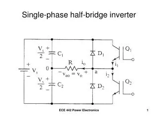
16. 16 Demonstration circuit Freq. inverter
Step 2: regeneration of 3-Phase-signals
Six switches
Generate periodic pulse-trains;
Insulated Gate Bipolair Transistor (IGBT);
High frequency switches;
17. 17 Demonstration circuit Freq. inverter
18. 18 Running the motor Direction
Direction (CCW or CW)
Can be changed by manipulating the pulses
19. 19 Running the motor Speed
Depends on the switching frequency
20. 20 Running the motor
Faster
1s time window
21. 21 Now you have learned;
There are different three-phase measurements.
What Pulse Width Modulation is.
Why Inverters mess-up with Period Time T.
22. 22