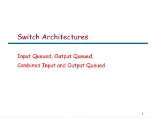
Switch Fabric Architectures Vahid Tabatabaee Fall 2006
180 likes | 393 Views
Switch Fabric Architectures Vahid Tabatabaee Fall 2006. References. Light Reading Report on Switch Fabrics, available online at: http://www.lightreading.com/document.asp?doc_id=25989

Switch Fabric Architectures Vahid Tabatabaee Fall 2006
E N D
Presentation Transcript
Switch Fabric Architectures Vahid Tabatabaee Fall 2006
References • Light Reading Report on Switch Fabrics, available online at: http://www.lightreading.com/document.asp?doc_id=25989 • Title: Network Processors Architectures, Protocols, and PlatformsAuthor: Panos C. LekkasPublisher: McGraw-Hill • Multi-Gigabit Serdes: The Cornerstome of High Speed Serial Interconnects, Genesys Logic America, Inc. • C. Minkenberg, R. P. Luijten, F. Abel, W. Denzel, M. Gusat, Current issues in packet switch design, ACM SIGCOMM Computer Communication Review, Volume 33 , Issue 1 (January 2003)
Two Chip Architecture • The switch interface (queue manager) chip resides on the line card • Interface with the traffic manager and/or Network Processor. • Transmit and receives cells from the switch chip through the backplane. • Queues and schedules cells in the ingress and egress side. • The switching element chip resides on the switch card. • Transmit and switch cells between the line cards. • Temporary buffers cells.
Two Chip Architecture • The switching element can have buffer (Shared memory, Buffered Crossbar) or buffer-less (cross-bar) • Data, flow control and queue info. is sent between chips. • Generally flow-control from the chip with lower memory to the one with larger memory is more critical.
Backpressure Flow Control • Backpressure flow control is to avoid buffer flow in receiving chips. • Suppose that the receiving chip does not have any more memory space. • It sends the backpressure flow control message to the transmitting chip to avoid sending anymore cells. • If there are multiple queues it will desirable to specify which queue is full. • We can start sending the backpressure signal before queue is full to lower the transmission rate (rate-based flow control) • As the queue gets fuller we send the backpressure signal more frequently to decrease the transmission rate more and more.
Backpressure Flow Control • We can have different threshold values for flow-control of different queues. • In the switch fabric, multiple line-card are transmitting to a switching chip. • It is desirable to back-pressure each one separately. • Therefore, we need per-input, per-class queueing in the switch chip. • For a 32x32 system with 8 classes of service • How many ingress queues do we need in the interface chip? • How many do we need in the switching chip? • Do we need to assign higher threshold value to the high priority queue or to the low priority queue?
Latency, Flow Control issues • The aggregate throughput of the routers are increasing • The trend is usually increasing number of ports rather than port speed. • This means that we need to increase line-cards • The switch fabric can no longer be built in a single rack • Racks can be tens of meters apart. • We need to spend more power for signal transmission. • This yields to higher RTT inside a switch Source: Ref. 4 (Current Issues in Packet Switch Design
Latency, Flow Control issues • The latency is time in flight (backplane or cable) and the pipeline logic and serdes delay. • The increased RTT means more packets in flight that should be taken into account for buffering requirements. Source: Ref. 4 (Current Issues in Packet Switch Design
Backpressure Flow Control and Latency • We have to be careful about latency in setting the flow control thresholds. • After sending the flow control signal, we can still get up to 2K cells. • Therefore, the threshold could not be larger than buffer size - 2K. • The problem is more serious in multi-rack systems. • We have to take the inside chip hardware delay into account. • This could be a serious problem for buffered-crossbar architectures since they have limited memory per-queue.
Shared Memory Switch Fabric • The switching chip has a large size memory. • The line interface schedule one of the queues that are not back-pressured and send the cell to the swicth chip. • Switch chip buffers the incoming cells into the memory. • Since every line port can send a cell we have to write N cells in every time slot. • There are N schedulers working in parallel in the switch chip (one per output port). • Ideally we need to have 1 queue for each class, input and output port. • Practically in many systems we only have per output and class queue.
Shared Memory Advantages • The scheduling is always a many-to-one problem. • It can efficiently support multi-cast. • The memory is shared between queues. • We can achieve high throughput in this system, since there is no contention as long as we have enough memory. • There is no need for transmission synchronization between ingress ports.
Disadvantages of Shared Memory • Scalability problems: • Number of queues in the switch chip is NxNxC • N writes and N reads from the memory in one time slot. • N schedulers in the same chip. • It is hard to design a cell slice, shared memory switch fabric (why?) • The only appropriate redundancy model is 1+1 (why?) • The flow control mechanism should be sophisticated.
Buffered Crossbar Architectures • For each input-output pair a separate memory is used. • Instead of one big memory we have N2 small memories. • Therefore, at every time slot we are writing and reading at most one cell from each memory. • There is no contention between memories.
Advantages of Buffered-Crossbar • We do not need memory speed-up since every memory should work at line speed. • There is no contention between input and output ports since each one is using separate memories. • We have distinct queues for input-output connections that is necessary for providing differentiated services between queues. • We only need to perform many-to-one scheduling. • Theoretically, we can achieve 100% throughput.
Disadvantages of Buffered Crossbar • We need NxNxC queues in a single chip. • We need NxN distinct memories in a single chip. • For a 32 port switch, we need 1024 memories. • Depth of the memories can not be so large. • This results in Flow Control Problems. • In order to control number of queues we have to limit number of Classes. • We need to take byte-slice approach for speed-up. • This means we have to synchronize switch chips. • It seems that 1+1 is the only appropriate redundancy model.