Comprehensive Overhaul and Development of Target Tracking Equipment for ECE 445
This project focuses on the quick overhaul of target tracking equipment, including hardware and software interfaces for tracking target positions. Key objectives include collecting video signals to analyze wing-beat signatures, ensuring design safety and reliability for fieldwork, and completing successful field tests. Modifications to previous ECE 445 designs are incorporated, along with real-time data processing for accurate target tracking. The project also acknowledges contributions from team members and emphasizes future development for operational effectiveness.

Comprehensive Overhaul and Development of Target Tracking Equipment for ECE 445
E N D
Presentation Transcript
INHS Tracking Radar ECE 445 – Team 7 4.27.06 David Grunschel Niket Nathani
Proposal • Perform quick overhaul of equipment • Build hardware and software interface for tracking target position • Collect video signal to obtain wing-beat signatures • Make design safe and reliable for field work • Field test completed design
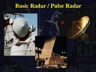
Original Design Ideas • Receive position data and select with • multiplexer • Use PCI-DAS 4020 with 20 MHz analog I/O and 24 TTL I/O lines for obtaining video and position data on the same board • Modify previous ECE 445 student’s code
Doing What it Takes • # trailers cleaned: 1 • # trailer cabs cleaned: 1 • # pedestals erected: 1 • # ckt boards cleaned: 20 • # chassis cleaned: 4 • # cables and surfaces cleaned: many • Working ECE 445 project: • Priceless.
Reverse Engineering • Previous User’s Interface Cable
Board 1A3A5 • Data Registers • ADDR Decoder • ADDR Register
Interface :: Hardware • PCI I/O Computer Board: • Measurement Computing CTR-05 • 8 TTL outputs • 8 TTL inputs • Capable of sinking 24 mA; plenty to override radar logic • Fast enough for our purpose
Interface :: Software • while ( ESC key not pressed ) { • for( all 12 data bytes ) { • Initialize control signals • Set ADDR bits A1-A4 • Load ADDR • Set intermediate quad buffer to high-Z • Activate ADDR decoder • Sample data register • Measure D0-D7 • } • Convert BCD digits to AZ, EL, RA, and TIM numbers ; • Write to datafile ; • Calculate coordinates for graphics display ; • Update graphics display ; • }
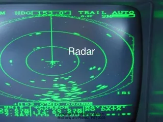
Interface :: Software :: Data Output File • Data output file format: • TIM AZ EL RA • 540 222.24 7.99 1372 • 541 222.24 7.99 1372 • etc. • Data file automatically saved with time • and date stamp
Interface :: Software :: Graphics • Features • Real-time • Windowed • Easy-to-interpret displays • Observable motion of target • Practical scale parameters • Thanks to Jon Johnson, who • used OpenGL to write the C++ • code for the graphics display • from the detailed • specifications we gave him.
Testing • Power Supplies • Standalone Control Unit Operation • CTR-05 Board • Logic Voltage Levels • Response to Control Signals • Real-time Software Operation
Future Work • Get transmitter unit fully operational • Collect analog video signal and store • reflected power time series of target • Signal analysis of time series (Prof. Franke)
Thanks to: • Ron Larkin for everything, especially his enthusiasm • Ben Kamen for his vast knowledge of electronics, the use • of his equipment, and his time and support • Jonathan Johnson for his amazing programming skills and his time • Dan Mast for advice on board cleaning and the use of his equipment • Scott Anderson and Scott Carney for their support and belief • in our abilities