Download
1 / 26
260 likes | 384 Views
Status of the optical cavity R&D at ATF. T.Takahashi Hiroshima University for collaborators. IWLC2010 Geneva 20-October-2010. an idea. Klemiz , Monig. an idea. Klemiz , Monig. no dedicated R&D program for photon colliders

E N D
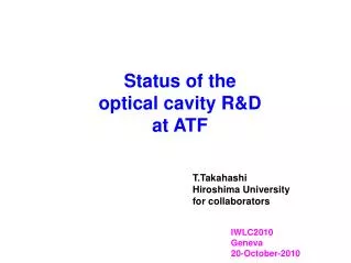
Status of the optical cavity R&D at ATF T.Takahashi Hiroshima University for collaborators IWLC2010 Geneva 20-October-2010
an idea Klemiz, Monig
an idea Klemiz, Monig no dedicated R&D program for photon colliders but projects for laser-Compton scattering with optical cavity Polarized positron sources x-ray sources
Prototype Cavities 2-mirror cavityat KEK ATF experiences with accelerator moderate enhancement moderate spot size simple control 4-mirror cavity at LAL 4-mirror test bed at KEK high enhancement, small spot size
Experimental R/D in ATF Hiroshima-Waseda-Kyoto-IHEP-KEK prototype 2-mirror cavity Lcav= 420 mm Put it in ATF ring
AFTER TILC09 slide at ALCPG09 • One of the Mirror was replaced with the higher reflectivity one • 99.6% -> 99.9% • power enhancement • 250 -> ~750 • more precise controll required (~0.1nm) • Status of the cavity w/ new mirror • Finess ~2000 with feedback on before vacuum on • now in preparation for beam • hope to get 3 times more photons by the end of the year 99.9% 99.6%
W/ Larger enhancement cavity in 2009 10.8g/train at 1 bunch (2.2ma) 26.8g/train10cunches(6.7mA) After, extensive studies; Power enhancement of the cavity ~ factor 3 Laser power 500W to 1.48kW The electron beam was not tuned enough in 2009 demonstration of 3 times more g by beam tuning bunch by bunch observation soon
to get higher enhancement and smaller beam waist 4 mirror cavity
We should go to 3D4 mirror ring cavityto get small sport size tospot size α 2d 4M has astigmatism 2 mirros is not stable for small spot size toposition in the cavity 3D (or twisted) 4M ring cavity
4M cavity test bed at KEK • in 4M ring cavity, photons travel twisted path. • got geometric phase • the cavity only resonate w L or R handed state • and more,,, optical feature of the 3D4M cavity is being studied on test bed
a parameter of the 4M cavity d: keeping circumference constant while changing distance between mirrors d d smaller d : smaller beam waist d d PD measure beam profile here-->estimate beam size in the cavity
calculated profile around focal point δ=0.2mm, z=0 z=-2mm z=-4mm focal point z=4mm z=2mm z=0mm profile is rotating during its propagation! angular momentum of light
spot size at the center of two focusing mirrors 計算結果 minor major smallest with this prototype 2σ=(52μm、43μm)
Profile of transmitted light major axis (calculation) minor axis (calculation) major axis (measurement) minor axis (measurement) measurements are consistent with calculation. find better solution
for smaller spot size plane mirror plane mirror spot size at focal point concave mirror concave mirror major axis minor axis
Summary good experience and g ray demonstration at the ATF with 2 mirror cavity progress understanding of 4 mirror ring cavity through prototype construction and calculation In near future setp by step and steady improvement more complicated but interestingfeature of 3D cavity • bunch by bunch information with 2 M cavity • 4M cavity in the ATF ring • LAL cavity installed -> prepared for collisions • KEK-Hiroshima type being designed
More enhancement More precise control (99.64%, 99.64%)to (99.64%, 99.94%) enhancement: 250 to 760 Witdh of resonant peak got down to 0.35nm from 0.60nm 変更前の共鳴度 変更後の共鳴度 0.60nm 0.35nm More precise(~faster) control of cavity cavity length [nm]
Feed back system in 2008 ATF RF Phase mon. PID Cavity レーザー光 Laser PI Res. Mon. Control: Laser to keep resonance Cavity for timing synchronization Keeping resonanceat 250 enhacement with timing jitter ~2ps 15ms Resonance 400μs Cont. signal 1.2 V Phase RMS~2 ps
Initial performance with760 enhancement 電子RF 位相モニタ PID制御回路 蓄積共振器 レーザー光 レーザー PID制御回路 共鳴モニタ Faster feed back to laser to keep resonance 共鳴 Larger fluctuation of laser timing 制御信号 RMS ~150ps timing control could not follow
New feedback system ATF RF Phase Mon PID Cavity 追加 レーザー光 PID Laser Res. Mon. New feedback control + improve emviromnet Timing jitter is now < 2ps 共鳴 RMS < 2 ps
at ALCPG09 3D 4M cavity resonates with left and right circular polarizaton separately This is due to geometric phase since light travels twisted path but situation was more complicated
Image rotation during light propagation M(z)=D(L/2).R(θ).F(f2,f1).D(L).R(θ).D(L).R(θ).D(L).R(θ).F(f1,f2).D(L/2)