Download
1 / 56
560 likes | 578 Views
Learn about the importance of the VELO RF shield in the LHCb Upgrade and the challenges involved in creating a thinner foil with a smaller aperture. Discover the proposed changes and the impact on machine aperture.

E N D
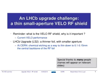
An LHCb upgrade challenge: a thinsmall-aperture VELO RF shield Reminder: what is the VELO RF shield, why is it important ? Current VELO performance LHCb Upgrade (LS2): a thinner foil, with smaller aperture At CERN: chemical etching as a way to thin down to 0.1-0.15mm the central backbone of the RF foil Special thanks to many people (names will appear on relevant slides)
Current VELO half with silicon detectors • CO2 cooling • Thin Al enclosure: the “RF shield” or “RF box”
VELO challenges: a reminder • Movable detector and yet very precise ! • Comes very close to the beams • Lives in an extreme and highly inhomogeneous radiation field • Must be cooled, in vacuum • Thin fragile wall between beam and detector volumes • Static and dynamic vacuum effects must be under control • Impedance and other RF effects must be under control
… and yet it worked like a charm! The RF foil! 4 um
Next, LHCb upgrade ! (2018-2019, LS2) Do at least as good as now, but in a harsher environment! • Higher luminosity and pile-up • Instantaneous lumi: L = 4e32 2e33 cm-2/s • Average nr of visible interactions per crossing: mu = 1.8 5.2 • This means more radiation and larger track density • Higher beam currents, 25 ns • RF / dynvac effects How ? • See VELO upgrade TDR ! • Pixel detector (instead of strips) • Smaller aperture (foil at 3.5 instead of 5.5mm) • Need of a more advanced cooling solution (microchannel substrates)
Compact VELO proposal • Motivation: we know now that the VELO-beam position stability/reproducibility are much better than we conservatively assumed up till 2010 (before having LHC beam experience). How can we profit from that for the LHCbUpgrade ? • Reducing the VELO distance of approach to the luminous region will make the Impact Parameter resolution better ! … Measurement errors (detector resolution) Multiple scattering error Extrapolation error Z1 Z2 Multiple scattering Impact parameter (IP) Impact parameter (IP) Deviated track True origin vertex True origin vertex How much better ?
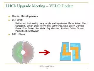
Motivation for VELO RF foil changes Aperture reduction velopix Thinning the central backbone
Reminder: how was the current minimum radius defined • Original definition of minimum radius for the RF foil (1998!!) • Decided to use RF foil inner radius of 5.5 mm See • wwwslap.cern.ch/collective/impedance.wkg/12-06-98/notes.ps Reconsider based on experience!
Achieved aperture (actual!) • VELO material distribution obtained from interactions in the material • Below, a visualisation of the true aperture. The solid black circle is the nominal aperture (5.5 mm radius). The dashed blue and red semi-circles correspond to the fitted circles found at each slot position, where the fitted radius has been reduced by 0.15mm to take into account the foil thickness. The dotted black circle is the true aperture of 4.9mm given by the combination of the fitted circles.
Position of luminous region vs VELO halves +/-20um mm +/-20um mm
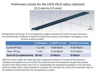
The new aperture Si radius (active area) Si guard ring ~ 0.5 mm Gap ~0.5 mm Rfoil,nominal Nominal beam axis RF foil thickness ~0.2-0.3 mm Impact on machine aperture Our aim: Si radius (active area) ~ 5.1 mm Need foil at ~3.5 mm
Main forum: LHC Experiment study group Thanks to Mark Galllilee • Proposal discussed at the LEB working group • 21st LEB meeting, 19 July 2012 https://indico.cern.ch/conferenceDisplay.py?confId=198975 • 22nd LEB meeting, 10 Sep 2012 https://indico.cern.ch/conferenceDisplay.py?confId=204787 • 23rd LEB meeting, 8 oct 2012 http://indico.cern.ch/conferenceDisplay.py?confId=209136 • 24th LEB meeting, 26 oct 2012 http://indico.cern.ch/conferenceDisplay.py?confId=212405 • Presented also to the “Parameter and Layout Committee” (HL-LC) • 2nd HL-LHC PLC on 25 september 2012 • Presented to LHCb TB 20thsep • VELO upgrade mini workshop in Santiago 19-20 Nov 2012 • LMC 159, 163 • LHCb VELO upgrade Technical Design Report http://cds.cern.ch/record/1624070
Aperture issue addressed • See ATS/LHCb note: It seems that 3.5 mm is a reasonable starting point for the RF foil Enough margin to incorporate yet unknown (but guestimated) tolerances
First impedance calculations Thanks to Benoit Salvant Transverse impedance is a strong function of radius (ZT ~ r-3)
Dynamic vacuum effects Thanks to Giulia Lanza • Static vacuum is not such an issue • LHC (beam lifetime) and LHCb (bkg) could easily survive with a stable pressure of up to 10-7 mbar (or more ?), while VELO easily can reach below 10-8 mbar. • But beams can affect the pressure ! • electron multipacting: free electrons are accelerated by the beam RF fields, hit the surfaces and release more electrons (or ions/atoms) • Ion bombardment: gas atoms are ionized and kicked to the surfaces, thus releasing more atoms • Synchrotron radiation also releases particles from the surfaces • These effects, under certain circumstances, can run away • See e.g. in “LHC vacuum system”, O. Gröbner, CERN-OPEN-2000-288 CAS - CERN Accelerator School : Vacuum Technology, Snekersten, Denmark, 28 May - 3 Jun 1999, pp.291-306, https://cdsweb.cern.ch/record/455985. • TE-VSC group (G. Lanza) can compute these effects Now converging toward a final RF foil design. We need feedback from BE-ABP (impedance) and TE-VSC (dynvac)
The new RF box (for the upgrade) NOT FINAL!! STILL BEING DISCUSSED
RF foil (box): current boxes installed • Production method: (NIKHEF/VU) • High pressure & temperature deformation • AlMg3 0.3mm foils (0.5mm sides) • Weld five foils together • Coat interior with Torlon • Difficult • Time-consuming (much trial & error) • Non perfect results (small imperfections in the welds) • Inhomogeneous density and thickness • But the boxes work !! • (zero problem encountered so far) A lot of information here: http://www.nikhef.nl/pub/departments/mt/projects/lhcb-vertex/ http://www.nikhef.nl/pub/departments/mt/projects/lhcb-vertex/prototypes/secondary_foil/
RF foil (box): new production R&D • New production method is being • studied: (NIKHEF/VU) • Mill the shape out of a block (5-axis precision milling machine) • Deckel-Maho DMF 260 FD • More flexibility to change the shape • Especially important for the pixel option (L-shape box) • Prototype shown here (one of two) • Wall thickness 0.3 mm (hope to reach 0.2 mm) • Leak tightness: good for one box, small leak in other (repair options to be investigated) • Mechanical tolerances: to be assessed A lot of info on http://www.nikhef.nl/pub/departments/mt/projects/lhcb-vertex/ http://www.nikhef.nl/pub/departments/mt/projects/lhcb-vertex/production/UpgradeRFbox/
Material choice Thanks to FlorianneLeaux and Gonzalo Izquierdo Current baseline: • Now trying a product from Alimex: AlMg4.5Mn0.7 “ACP5080RS”, (proprietary smelting method that allows them to achieve similar material quality as for cast or rolled blocks.), close to EN AW-5083, according to DIN EN 573-3/3.3547 • This product could turn out to be a cost effective alternative to standard cast/rolled products • NB: what costs here is mainly the precise machining time • Should have: good milling properties, very low porosity, high electric conductivity, good welding properties, no internal stress, clean vacuum properties during short baking at 150 (200) degrees. • We will try to perform tests on several samples • Will request company to perform qualitycontrol • sample micrography and perhaps ultrasound • LHCb of course very interested to obtain help from local CERN experts on this • frequently worked with Imbach in Switzerland (?)
What if ... What if thickness of final product cannot be made less than 200um or even 300 um ? Can we try to thin it down locally ? How ? => chemical etching (CERN, TE-VSC)
Why not tried earlier ? • Microstructure of stretched (hot formed) foils did not look encouraging for etching (and we had not enough time for R&D) • Also: thickness and density is not homogeneous over the corrugations
Whatneeds to bethinned ? • Most particles do not at all go through the side corrugations! • This regionis the most important and needs to bethinned down (~50mm wide) ~100cm ~20cm
Thinning by chemicaletching The ideais to «post-process» the RF box • a box isproduced in Amsterdam • CERN (TE-VSC) has the infrastructure/labs to makechemicaletching of large objectssuch as our RF box • Started investigations withNaOH • How wellcan the thicknessbelocallycontrolled on complexcorrugatedshapes ? • Microleaks ? • Afteretching, the box must becoatedwithelectricallyisolating layer (detector side) and NEG (beamside, heattreaments!) • It must undergoseveral "pressure/temperature" cycles duringitslifetime
R&D programme at CERN • Designed a smallsample RF foil withchuck/support • VELOstriplike, for historicalreasons... • Producedit by precisionmachining • aim for 0.3mm thickness • Made, 1 proto + 3 samples • Then: • Vacuum-test • Metrologize • Etch • Vacuum-test • Metrologize • Bake-out • Vacuum-test • Metrologize • Aim of metrology: extractthickness, check geometry, homogeneity of etching, etc about 20cm
Whatwe have Thanks to Olivier Jamet and EN-MME • 4 samples • sample0 (proto) : defect in machining, used for etching test and metro • sample1 , 2, 3: visually OK, vac OK • sample1processed: vac metroetchvac metro bakemetrovac • sample2 : vac metro bake metrovac • one counterpiece / vacchuck • one extension piece for etching
Etching Thanks to Leonel Ferreira, Lucia Amador & Pierre Maurin see also Derk van Dieten'spresentation, VELO meeting, 27-sep-2013
Thickness by precisemetrology Thanks to Didier Glaude 38 scans per data set: • 6 z-scans over each central bulge nr 1 to 6 • 6 y-scans over each bulge nr 7 to 12 • 7 y-scans over eachneck nr 13 to 19 • repeat for otherside thicknessobtainedfrom comparison of bothsides I define "my axes" as in LHCb...
Sample 3 1 2 3 4 5 6 History: • vacuum test • metrology "raw" Legend: Emptyisthicknessobtainedfrommetrology s/w directly Filledisthicknesswhich I calculatedfrom "position and deviation" data (as a cross check for sample 1, seelater...) each y-scan is offset by incremental +35mm for clarity 7 8 9 10 11 12 Z (1-6) Y (13-19) Y (7-12) note: thicknessspreadfrom the start 0.31 mm +/- 0.07mm (not to belaterattributed to etching!) 13 14 15 16 17 18 19
Sample 2 1 2 3 4 5 6 History: • vacuum test • metrology "raw" • bake-out • metrology "baked" • vacuum test 7 8 9 10 11 12 Z (1-6) Y (13-19) Y (7-12) 13 14 15 16 17 18 19
bake-out Thanks to Patrick Lepeule, Miguel Gil Costa, Agostino Vacca • sample 1 (etched) and sample 2 (raw) for comparison time Temp. 50 oC/h up, to 180 oC, 24h
Difference 1 2 3 4 5 6 sample 2 • shown here is the thickness difference between the "raw" and the "baked" (i.e. after bake-out) • reminder: this piece was not etched 7 8 9 10 11 12 13 14 15 16 17 18 19
Sample 1 1 2 3 4 5 6 History: • vacuum test • metrology ("raw") • etching • vacuum test • metrology ("etched") • bake-out • metrology ("baked") • vacuum test Problemwithmy "etched" data ?? => I checked vs Didier's direct thickness data for nr 6, 7 & 14 (seenextslides) => seems correct ... => wrongmeasurement ??? NB: these values should correspond! (scan crossing point) 7 8 9 10 11 12 Z (1-6) Y (13-19) Y (7-12) 13 14 15 16 17 18 19
Difference sample 1 • shown here is the thickness difference between the "raw" and the "baked" (i.e. after etching and bake-out) • Inhomogeneity of etching stays within +/-15um. 1 2 3 4 5 6 7 8 9 10 11 12 13 14 15 16 17 18 19
First conclusions from first etching test • Expected etched away mass (from geometry) checked by weight measurement and chemical balance. Good agreement. (Derk vD) • Etching of corrugated shape can be sufficiently homogeneous for our purpose (less than +/-15 um inhomogeneity) • Bake-out does not affect foil • vacuum tightness checked ok • Some unresolved discrepancies (?) in the metrology data • possibly due to software ? • possibly due to dirt ? • but then: why disagree on the crossing point of scans ? • anyway, discrepancies are of the order of 20 um
Status of four samples • Sample 0: defectuous production, used for test etching • Sample 1: etched, baked out, now being pressure cycled • Sample 2: baked out, now being pressure cycled • Sample 3: etched (first pass), will then try a second pass
Next • Try etching on an L-shaped sample (to be arranged with Amsterdam) • make a design (short length sample with a flange) NIKHEF ? • get material from/via NIKHEF (identical to final) • mill at CERN • Make (more sensitive) in-vacuum leak tests of samples 1, 2, 3 (NIKHEF) • check leaks with foil volume inside other vacuum volume • possible to cycle diff pressure from -10 to +10 mbar ? (to check no crack development at etching boundary… «fissuring») • Test torlon coating and NEG coating ? (CERN, TE-VSC) • on samples 1 and 2 ? • Test sequential etchings on Sample 3 ? (20mm, then 40mm strip) • Reproducibility/reliability ? • How to be confident that we will not fail on the final piece ? • More general: must reactivate wakefield and vacuum simulations at CERN with final pixel foil geometry • Import CAD design into simulations
fissuring ? • Could pressure/temperature cycles seed cracks at the ridge ? • In this case, a fuzzy-styledutchpainterwouldbebetterthan a sharp-geometricdutchpainter • And that'swhatwehad for now. ?? 300um 150 um (in fact, Mondrian alsostartedwithfuzzypaintings...)
300um 150 um
proposed pressure cycle test • First determine the acceptable pressure difference based on foil displacement ~ 0.1mm (suppose here it's ~10mbar) • Mount foil onto a flange to make a sealed "detector volume" and mount this volume into a tank. • Inject helium alternatively into the tank or into the "detector volume", producing the desired pressure difference. • Same time, continuously check leaking • Cycle ~50 times.
Next: anothershape • current VELO (silicon microstrip sensors) • upgrade VELO (pixel modules) • Different shape related to different sensor module geometry • Not expected to matter for etching, but need to check
Summary and conclusions • The RF shield is crucial in the VELO design • Dominates multiple scattering effects on resolution • It is THEinterface to the LHC beams • Going for aperture of 3.5 mm (now was 5.5 mm) seems possible • Milling from a block appears to be a viable solution • Material choice is important • Achievable thickness to be estalished (200 um ? 300 um ?) • Foil thinning by local etching seems also feasible • Establish etching procedure (down to 150 um) • Now trying to make the final optimization the RF shield and detector geometry • Z positions of stations, modules orientation/rotation • Impedance & dynvaceffects to be addressed Cooperation with TE-VSC, EN-MME, BE-ABP(…) is essential and much appreciated