Download
1 / 59
610 likes | 766 Views
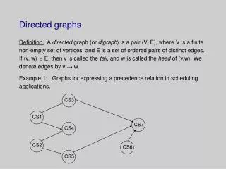
Scheduling and Directed Graphs. Notes 5 – Sections 8.1 & 8.2. Essential Learnings. Students will understand the key concepts and terminology of combinatorial scheduling. Students will understand and be able to use digraphs to represent problems. Principal Characters in Scheduling.

E N D
Scheduling and Directed Graphs Notes 5 – Sections 8.1 & 8.2
Essential Learnings • Students will understand the key concepts and terminology of combinatorial scheduling. • Students will understand and be able to use digraphs to represent problems.
Principal Characters in Scheduling Processors- the “workers” who carry out the work. Processors need not be humanbeings. In scheduling, a processor could just as well be a robot, a computer, an automated teller machine, and so on. We will use N to represent the number of processorsand P1, P2, P3,…, PN to denote the processors themselves. We willassume throughout the chapter that N ≥ 2.
Principal Characters in Scheduling The tasks – in every complex project there are individual pieces of work, often called “jobs” or “tasks.” We will define a task as an indivisible unitof work that (either by nature or by choice) cannot be broken up into smallerunits. Thus, by definition a task cannot be shared–it is always carried out bya single processor. In general, we will use capital letters A, B, C, …, to represent the tasks, although in specific situations it is convenient to use abbreviations (such as WE for “wiring the electrical system”).
Principal Characters in Scheduling At a particular moment in time a task can be in one of four possiblestates: • ineligible (the task cannot be started because some of the prerequisites for the task have not yet been completed), • ready (the task has notbeen started but could be started at this time), • in execution (the task isbeing carried out by one of the processors), • completed.
Principal Characters in Scheduling The processing time of a given task X is the amount oftime, without interruption, required by one processorto execute X. Whendealing with human processors, there are many variables (ability, attitude,work ethic, etc.) that can affect the processing time of a task, and this addsanother layer of complexity to an already complex situation.
Principal Characters in Scheduling On the otherhand, if we assume a “robotic” interpretation of the processors (eitherbecause they are indeed machines or because they are human beings trainedto work in a very standardized and uniform way), then scheduling becomessomewhat more manageable.
Principal Characters in Scheduling To keep things simple we will work under the following three assumptions: ■Any processor can execute any task (the versatility assumption). ■The processing time for a task is the same regardless of which processor isexecuting the task (the uniformity assumption). ■Once a processor starts a task, it will complete it without interruption (the perseverance assumption).
Principal Characters in Scheduling Under the preceding assumptions, the concept of processing time for a task(we will sometimes call it the P-time) makes good sense – and we can conveniently incorporate this information by including it inside parentheses next to thename of the task.
Principal Characters in Scheduling Thus, the notation tells us that the task called X(5) has a processing time of 5 units (minutes, hours, days, or any other unit of time)regardless of which processor is assigned to execute the task.
Principal Characters in Scheduling The precedence relations – formal restrictions on theorder in which the tasks can be executed, much like those course prerequisites in the school catalog that tell you that you can’t take course Y until youhave completed course X.
Principal Characters in Scheduling In the case of tasks, these prerequisites are calledprecedence relations. A typical precedence relation is of the form task X precedes task Y (we also say X is precedentto Y), and it means that task Y cannot be started until task X has been completed.
Principal Characters in Scheduling A precedence relation canbe conveniently abbreviated by writing XgY,or described graphically asshown. A single scheduling problem can have hundreds or eventhousands of precedence relations, each adding another restriction on thescheduler’s freedom.
Principal Characters in Scheduling It also happens fairly often that there are no restrictions on the order of execution between two tasks in a project. When a pairof tasks X and Y have no precedence requirements between them (neitherX g Y nor Y g X), we say that the tasks are independent.
Principal Characters in Scheduling Independent tasks: either one can be started before the other one, or they canboth be started at the same time. Graphically, we can tell that two tasks are independent if there are no arrowsconnecting them.
Principal Characters in Scheduling Precedence relations are transitive:If X g Y and Y g Z then it must betrue that X g Z.
Principal Characters in Scheduling We willmake a distinction between two types of precedence relations:basic andimplicit. • Basic precedence relations are the ones that come with the problemand that we must follow in the process of creating a schedule. • If we do this,the implicit precedence relations will be taken care of automatically.
Principal Characters in Scheduling We cannot have a set of precedence relationsthat form a cycle! Imagine having to schedule the tasks shown: X precedes Y, which precedes Z, which precedes W, which in turn precedesX. Clearly, this is logically impossible. From here on, we will assume thatthere are no cycles of precedence relations among the tasks.
Principal Characters in Scheduling Processors, tasks, processing times, and precedence relations are the basic ingredients that make up a scheduling problem. They constitute, in a manner ofspeaking, the hand that is dealt to us. But how do we play such a hand? To get asmall inkling of what’s to come, let’s look at the following simple example.
Example – Repairing a Wreck Imagine that you just wrecked your car, but thank heavens you are OK, and theinsurance company will pick up the tab. You take the car to the best garage intown, operated by the Tappet brothers Click and Clack(we’ll just call them P1 and P2). The repairs onthe car can be broken into four differenttasks: • exterior body work (4 hours), • engine repairs (5 hours), • paintingand exterior finish work (7 hours), • transmission repair (3 hours).
Example – Repairing a Wreck The onlyprecedence relation for this set of tasks isthat the painting and exterior finish workcannot be started until the exterior body work has beencompleted AgC. The two brothers always work together on a repair project, but each takes on a different task (so they won’t argue with each other).Under these assumptions, how should the different tasks be scheduled? Whoshould do what and when?
Example – Repairing a Wreck Below is a schedule that is very inefficient. All the short tasks are assigned to one processor (P1) and all the long tasks to the other processor (P2) –obviously not a very clever strategy. Under this schedule, the project finishing time(the duration of the project from the start of the first task to the completion of thelast task) is 12 hours.
Example – Repairing a Wreck We will use Fin to denote the project finishing time, forthis project we write Fin = 12 hours. Here’s what looks like a much better schedule, but it violates theprecedence relation AgC (as much as we would love to, we cannot start task Cuntil task A is completed).
Example – Repairing a Wreck On the other hand, if we force P2 to be idle for one hour, waiting for the green light to start task C, we get a perfectly good schedule. Under this schedule the finishing time of the project is Fin = 11hours.
Example – Repairing a Wreck That schedule is an improvement over the first schedule.Can we do even better? No! No matter how clever we are and no matter how manyprocessors we have at our disposal, the precedence relation A(4) gC(7) impliesthat 11 hours is a minimum barrier that we cannot break – it takes 4 hours to complete A, 7 hours to complete C, and we cannot start C until A is completed!
Example – Repairing a Wreck Thus, thatschedule is an optimal schedule and the finishing time of Fin = 11hours is the optimal finishing time. (Use Opt in place of Fin.) Here’s adifferent optimal schedule with finishing time hours Opt=11.
Two Useful Lessons As scheduling problems go, the previous example was a fairly simple one. But evenfrom this simple example, we can draw some useful lessons. First, notice thateven though we had only four tasks and two processors, we were able to createseveral different schedules.
Two Useful Lessons Second, there is an absolute minimum time that no schedule can break, no matter how good an algorithm we use or how many processorswe put to work. Every project, no matter how simple or complicated, has an absolute minimum (called the critical time) that dependson the processing times and precedence relations for the tasks and not on thenumber of processors used.
Two Useful Lessons In looking for agood, or even an optimal, schedule, we are going to need a systematic way to sortthrough the many possibilities. In other words, we are going to need some goodscheduling algorithms.
Example – Building That Dream Home On Mars It is the year 2050, and several human colonies have already been established onMars. Imagine that you accept a job offer to work in one of these colonies. Whatwill you do about housing?
Example – Building That Dream Home On Mars Like everyone else on Mars, you will be provided with a living pod called a Martian Habitat Unit (MHU). MHUs are shipped to Mars in the form of prefabricatedkits that have to be assembled on the spot – an elaborate and unpleasant job if youare going to do it yourself.
Example – Building That Dream Home On Mars A better option is to use specialized “construction” robotsthat can do all the assembly tasks much more efficiently than human beings can. These construction robots can be rented by the hour at the local Rent-a-Robotoutlet.
Example – Building That Dream Home On Mars The assembly of an MHU consists of 15 separate tasks, and there are 17 different precedence relations among these tasks that must be followed. The tasks,their respective processing times, and their precedent tasks are all shown next.
Example – Building That Dream Home On Mars Here are some of the basic questions we will want to address: How can weget your MHU built quickly? How many robots should you rent to do the job? How do we create a suitable work schedule that will get the job done?
Example – Building That Dream Home On Mars A robotwill do whatever it is told, but someone has to tell it what to do and when. These are all tough questions to answer, but we will be able to do it later in thechapter.
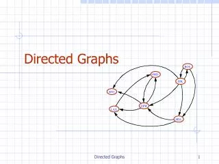
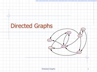
Directed Graphs Section 8.2
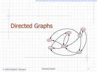
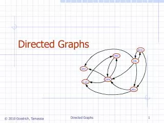
Directed Graph or Digraph A directed graph, or digraph for short, is a graph in which the edges have adirection associated with them, typically indicated by an arrowhead. Digraphs areparticularly useful when we want to describe asymmetric relationships (X relatedto Y does not imply that Y must be related to X).
Directed Graph or Digraph In a digraph, instead of talking about edges we talk about arcs. Every arc isdefined by its starting vertex and its ending vertex, and we respect that orderwhen we write the arc. Thus, if we write XY, we are describing the arc , as opposed to the arc YX .
Directed Graph or Digraph A list of all the arcs in a digraph is called the arc-set of the digraph. This digraphhas arc-set A= { XY, YX }. If XY is an arc in the digraph, we say that vertex X is incident to vertex Y, or,equivalently, that Y is incident fromX). The arc YZ is said to be adjacent to the arc XY if the starting point of YZ isthe ending point of XY. (Essentially, this means one can go from X to Z byway of Y).
Directed Graph or Digraph In a digraph, a path from vertex X to vertex W consists of a sequence of arcsXY, YZ, ZU ,…,VW such that each arc is adjacent to the one before it andno arc appears more than once in the sequence – it is essentially a trip fromX to W along the arcs in the digraph. The best way to describe the path is bylisting the vertices in the order of travel: X, Y, Z, and so on.
Directed Graph or Digraph When the path starts and ends at the same vertex, we call it a cycle of thedigraph. Cycles in digraphs can be writtenin more than one way – the cycle X, Y, Z, X is the same as the cycles Y, Z, X, Yand Z, X, Y, Z.
Directed Graph or Digraph In a digraph, the notion of the degree of a vertex is replaced by the conceptsof indegree and outdegree.
Directed Graph or Digraph The outdegree of X is the number of arcs that haveX as their starting point(outgoing arcs); The indegree of X is the number ofarcs that have X as their ending point (incoming arcs).
Example – Digraph Basics This digraph has vertex-set V= {A, B, C, D, E} and arc-set A= {AB, AC, BD,CA, CD, CE,EA, ED}. In this digraph,A is incident to Band C, but not to E. By the same token, A is incident from E as well as from C.
Example – Digraph Basics The indegree of vertex A is 2, and so is the outdegree. The indegree of vertex Dis 3, and the outdegree is 0.
Example – Digraph Basics In this digraph, there are several paths from A to D, such as A, C, D; A, C, E, D; A, B, D; and even A, C, A, B, D. On the other hand, A, E, D is not a path fromA to D (because you can’t travel from A to E).
Example – Digraph Basics There are two cycles in thisdigraph: A, C, E, A (which can also be written as C, E, A, Cand E, A,C,E), and A,C,A. Notice that there is no cyclepassing through D because D has outdegree 0 and thus is a“dead-end,” and there is no cycle passing through B becausefrom B you can only go to D.
Applications of Digraphs Traffic Flow In most cities some streets are one-way streets and others aretwo-way streets. In this situation, digraphs allow us to visualize the flow oftraffic through the city’s streets. The vertices are intersections, and the arcsrepresent one-way streets. To represent a two-way street, we use two arcs,one for each direction.