KINEMATIC CHAINS & ROBOTS (I)
250 likes | 282 Views
KINEMATIC CHAINS & ROBOTS (I). Kinematic Chains and Robots (I).

KINEMATIC CHAINS & ROBOTS (I)
E N D
Presentation Transcript
KINEMATIC CHAINS & ROBOTS (I)
Kinematic Chains and Robots (I) • This lecture continues the discussion on a body that cannot be treated as a single particle but as a combination of a large number of particles. Many machines can be viewed as an assemblage of rigid bodies called kinematic chains. This lecture continues the discussion on the analysis of kinematic chains with focus on robots. • After this lecture, the student should be able to: • Appreciate the concept of kinematic pairs (joints) between rigid bodies • Define common (lower) kinematic pairs • Distinguish between open and closed kinematic chains • Appreciate the concept of forward and inverse kinematics and dynamics analysis • Express a finite motion in terms of the transformation matrix
Rotation Translation Axis of rotation passes through the point Axis of rotation The angle of rotation The displacement component parallel to the direction of rotation General Rigid-Body Motion = + General Motion The general motion is equivalent to that of the action of a screw, which can be described using 4 “screw” parameters:
General Rigid-Body Motion • Chasles Theorem: • A general finite rigid-body motion is equivalent to • A pure translation (sliding) along, by an amount us, and • A pure rotation about the axis of rotation, by an amount The general rigid-body motion can be characterized by the screw parameters
If given find General Rigid-Body Motion Given R, we can solve for the eigenvector of R corresponding to =1 to get where I is the 33 identity matrix i.e. solve Get from
The displacement component of the motion parallel to is General Rigid-Body Motion The previous deals with rotation. In general, if we are given the location of a point C at 2 time instance, i.e. given and We can denote the motion of the point C due to both rotation and translation as Finally:
Kinematic Pair • A kinematic pair is the coupling or joint between 2 rigid bodies that constraints their relative motion. • The kinematic pair can be classified according to the contact between the jointed bodies: • Lower kinematic pairs: there is surface contact between the jointed bodies • Higher kinematic pairs: the contact is localized to lines, curves, or points
y x Revolute/pin joint Planar joint s s Spherical joint Cylindrical joint Prismatic joint Lower Kinematic Pairs
Kinematic Chain • A kinematic chain is a system of rigid bodies which are joined together by kinematic joints to permit the bodies to move relative to one another. • Kinematic chains can be classified as: • Open kinematic chain: There are bodies in the chain with only one associated kinematic joint • Closed kinematic chain: Each body in the chain has at least two associated kinematic joints • A mechanism is a closed kinematic chain with one of the bodies fixed (designated as the base) • In a structure, there can be no motion of the bodies relative to one another
Kinematic joint Base (fixed) Structure Rigid bodies Closed kinematic chain Open kinematic chain Open and Closed Kinematic Chains
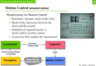
Robots Robots for manipulation of objects are generally designed as open kinematic chains These robots typically contain either revolute or prismatic joints
Link (2) Link (3): Gripper Link (1) A Simple Planar Robot Link (0): Base This simple robot will be used throughout to illustrate simple concepts
Y3 X3 Y0 2=90° X0 Forward Kinematics Analysis Consider the following motion: ? Y3 X3 Given the dimensions of the linkages and the individual relative motion between links, how to find the position, velocity, acceleration of the gripper? (Forward kinematics analysis problem)
Y3 2=?° X3 Y0 X0 Inverse Kinematics Analysis Again consider the following motion: Y3 X3 Given the dimensions of the linkages and the desired motion of the gripper, how to find the individual relative motion between links? (Inverse kinematics analysis problem)
Y3 2=?° and force required X3 Y0 X0 Dynamics Analysis Again consider the following motion: Y3 X3 Given the inertia and dimensions of the linkages and the desired motion of the gripper, how to find the individual relative motion between links and the actuator forces to achieve this motion? (Dynamic analysis problem)
C C X B X Z-axis Z-axis A A B We will denote the rotation matrix “R” that brings frame {a} to frame {b} as “O” “O” Y-axis Y-axis X-axis X-axis Notation Consider the following motion. We will associate basis vectors with frame {b} and the (X, Y, Z) axis with frame {a}
C X B Z-axis A “O” Y-axis X-axis Notation Example
C X B Z-axis A “O” Y-axis X-axis Notation The position of point “C” expressed in frame {a} is denoted by For example, is the position of point “C” relative to frame {b} expressed in terms of frame {a}
C X B Z-axis A “O” Y-axis X-axis Transformation matrix Consider the 2 frames {a} and {b}. Notice that for a vector Example:
We can simplify the above equation to: where is called the Transformation Matrix of frame {b} w.r.t. frame {a} is called the augmented vector Transformation matrix So far, in the example we used the origins of the two frames are at the same point. What if the origin of frame {b} is at a distance defined by the vector In this case, the point “B” is given by:
C X B Z-axis A “O” Y-axis X-axis Example: Transformation matrix What is the transformation matrix for the case below?
C X B Z-axis A “O” Y-axis X-axis Example: Transformation matrix
Transformation matrix and Position If R is the identity matrix, then there is no rotation and the transformation matrix will represent the pure displacement of the origins of the frames of reference:
Summary • Many machines can be viewed as an assemblage of rigid bodies called kinematic chains. This lecture continues the the discussion on the analysis of kinematic chains with focus on robots. • The following were covered: • The concept of kinematic pairs (joints) between rigid bodies • Definition of common (lower) kinematic pairs • Open and closed kinematic chains • The concept of forward and inverse kinematics and dynamics analysis • Finite motion in terms of the transformation matrix