Chapter 42: Thread and Gear Manufacturing
330 likes | 657 Views
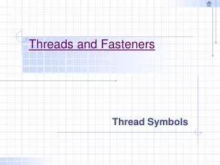
Chapter 42: Thread and Gear Manufacturing. DeGarmo’s Materials and Processes in Manufacturing. 42.1 Introduction. FIGURE 42-1 Standard screwthread nomenclature. Fig. 29-A Symbols for threads. A, Unified system. B, ISO system

Chapter 42: Thread and Gear Manufacturing
E N D
Presentation Transcript
Chapter 42: Thread and Gear Manufacturing DeGarmo’s Materials and Processes in Manufacturing
42.1 Introduction FIGURE 42-1 Standard screwthread nomenclature.
Fig. 29-A Symbols for threads. A, Unified system. B, ISO system (Source: P.F. Ostwald and J. Munoz, Manufacturing Processes and Systems, John Wiley & Sons, 1997)
UN Thread Example 1 (nominal diameter less than 1/4 in) 4 - 40 UNC A number (1 through 12) is used for a thread having its nominal diameter less than 1/4 in. UNC: coarse thread Threads/in Nominal size (#4 thread: major diameter = 0.111 in) 4 - 48 UNF UNF: fine thread Threads/in Nominal size (#4 thread: major diameter = 0.111 in)
UN Thread Example 2 (nominal diameter more than 1/4 in) 1/2 - 13 UNC UNC: coarse thread Threads/in Nominal size (major diameter = 0.5 in) 1/2 - 20 UNF UNF: fine thread Threads/in Nominal size (major diameter = 0.5 in)
UN Thread Example 3 (nominal diameter = 4 in, Compare this with Example 1) 4 - 4 UNC UNC: coarse thread Threads/in Nominal size (major diameter = 4 in)
ISO Thread Examples M2.5 0.45 Pitch, mm Nominal size, mm (major diameter = 2.5 mm) M: M stands for ‘metric thread’ Some nominal size thread has several options for pitch size. For example, for M16 threads M16 2 M16 1.5
FIGURE 42-5 (below) Two ways to feed the threading tool into the workpiece. FIGURE 42-4 (above) Cutting a screw thread on a lathe, showing the method of supporting the work and the relationship of the tool to the work with the compound swiveled. Inset shows face of threading dial.
FIGURE 42-6 Canned subroutines called G codes are used on CNC lathes to produce threads. See Chapter 26 for CNC discussion.
FIGURE 42-7 (a) Solid threading die; (b) solid adjustable threading die; (c) threading-die stock for round die (die removed). (Courtesy of TRW-Greenfield Tap & Die.)
FIGURE 42-8 Self-opening die heads, with (a) radial cutter, (b) tangential cutters, (c) circular cutters, and (d) terminology of circular chasers and their relation to the work. (Courtesy of Geometric Tool Company, Warner & Sawsey Company, National Acme Company, and TRW-Greenfield Tap & Die, respectively.)
42.3 Internal Thread FIGURE 42-9 Terminology for a plug tap with photographs of taper (t), plug (p), and bottoming (b) taps, which are used serially in threading holes. (Courtesy of TRW Greenfield Tap & Die.)
FIGURE 42-10 (Left to right) Spiral-fluted tap; spiral-point tap; spiral-point tap cutting chips; fluteless bottoming tap and fluteless plug tap for cold forming internal threads; cross section of fluteless forming tap. (Courtesy of TRW-Greenfield Tap & Die.)
42.4 Thread Milling FIGURE 42-12 Thread milling on a three-axis NC machine can produce a complete thread in a single feed revolution. (Fred Mason, American Machinist, November, 1988.)
FIGURE 42-12 Thread milling on a three-axis NC machine can produce a complete thread in a single feed revolution. (Fred Mason, American Machinist, November, 1988.)
FIGURE 42-13 The process of high-speed thrilling (drilling plus threading) a hole includes (1) approach, (2) drill plus chamfer, (3) retract one thread pitch, (4) radially ramp to the major thread diameter, (5) thread-mill with helical interpolation, (6) return the tool to the centerline of the hole, and (7) retract from the finished hole. At 20,000 rpm, a hole can be thrilled in aluminum in less than two seconds. (Fred Mason, American Machinist, November, 1988.)
42.6 Thread Rolling FIGURE 42-14 Roll forming threads using flat die thread rolling process shown in (a) and (b). The threads forming action is shown in (c) and the product in (d). Three variations of cylindrical rolling are shown in (e), (f), and (g).
FIGURE 42-14 Roll forming threads using flat die thread rolling process shown in (a) and (b). The threads forming action is shown in (c) and the product in (d). Three variations of cylindrical rolling are shown in (e), (f), and (g).