Download
1 / 47
470 likes | 587 Views
PAC trigger in the high eta region based on the MPGD detectors – electronic system. GEMs for CMS High Eta - Workshop II , 24 June 2011. Three possibilities for the PAC trigger electronics upgrade . Option 1 Use the current RPC PAC Trigger Boards for the high eta

E N D
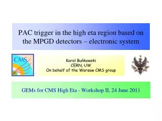
PAC trigger in the high eta region based on the MPGD detectors – electronic system GEMs for CMS High Eta - Workshop II, 24 June 2011
Three possibilities for the PAC trigger electronics upgrade • Option 1Use the current RPC PAC Trigger Boards for the high eta • Option 2Build new Trigger Boards for the high eta, but connect them to the current RPC PAC Trigger Crates • Option 3Build new RPC Trigger electronics for the entire detector Karol Buńkowski, CERN, UW,
Current RPC PAC Trigger system Karol Buńkowski, CERN, UW,
Link Board Link Board Link Board Synchronization Unit & LMUX FEB FEB FEB FEB FEB FEB RPC PAC muon trigger Detector Counting room Control & diagnostic LVDS cables Ghost Buster & Sorter Trigger Board GB & Sorter SYNCH. & LDMUX PAC Optic Links 90 m @ 1.6 GHz 1104fibers PAC 1232Link Boards in96Boxes, Steered byControl Boards To theGlobal Muon Trigger PAC Data Concentrator Card RMB To Data Acquisition 84Trigger Boards in12Trigger Crates Data transmission @ 320 MHz Resistive Plate Chambers Up to 6 layers of detectors. 480 chambers in barrel, 504 in endcaps * Numbers of elements for the staged version of the system Karol Buńkowski, CERN, UW,
Trigger CrateProcesses data from the detector wedge 30 (logic sector) in .Contains 7 Trigger Boards (staged system || <1.6), has slots for 2 additional TBs for the high eta region || <2.1 • Optical links from the detector are split and go to 2 or 4 TBs.
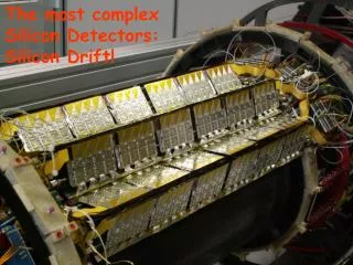
Trigger Board • Trigger Boardprocess data from the 3 or four towers of one logic sector. • 18 inputs of the optical links • 4 PAC chips (one chip per logic sector of one trigger tower) – trigger algorithm ALTERA STRATIX II (30 or 60). Currently (independently of upscope)new PAC TB mezzanine is designedto host ALTERA CYCLONE. • Readout MezzanineBoard – data acquisition • Complex and expensive board Karol Buńkowski, CERN, UW,
Phi segmentation Karol Buńkowski, CERN, UW,
Eta segmentation RE4/1 RE3/1 GE2/1 GE1/1(possibly doubled) GEMs for CMS High Eta - Workshop II, 24 June 2011
Pattern Comparator trigger algorithm • Chamber hits are compared with predefined set of patters obtained from the simulations. Patterns correspond to muons tracks of defined pT. Projective geometry is favoured with strip size of 2/1152 ≈ 0.3 deg • Muon candidate is generated when : • Barrel: • 3 out of 4 inner chamber layers are fired (to accept low pTmuons not reaching the outer stations) • 4 out of 6 (5) chamber layers are fired (high pTmuons) • Endcap • 3 out of 3 (4) chamber layers are fired and chamber hits fit to at least one pattern. The hits must be in the same BX • Muon position measurment: • In with granularity: ~0.2 (barrel) - ~0.12 (endcap). Eta unit is trigger tower, • In with granularity 1/144 × 2 ( = 0.223 rad = 2.5) . Phi unit is logical segment Karol Buńkowski, CERN, UW,
Trigger system for the high eta – integration with the current RPC PAC trigger system Karol Buńkowski, CERN, UW,
Versatile Link (a.k.a. G-Link system) • The electronic system for the high eta MPGD system will be (most probably) based on the G-Link • G-Link - new CERN project https://espace.cern.ch/project-versatile-link/public/default.aspxRadiation hard bi-directional optical link for use in the LHC upgrade program. The link targets data transmission between the on-detector and off-detector electronics serving simultaneously applications such as data acquisition, timing, trigger and experiment control: • GBT - radiation hard chipset http://cern.ch/proj-gbthttps://indico.cern.ch/getFile.py/access?contribId=4&resId=0&materialId=slides&confId=132452 • GLIB - Gigabit Link InterfaceBoardhttps://espace.cern.ch/project-GBLIB/public https://indico.cern.ch/getFile.py/access?contribId=5&resId=0&materialId=slides&confId=136793
GLIB - Gigabit Link InterfaceBoard • Mid-size double-width Advanced Mezzanine Card (AMC) • Serves as an evaluation platform and an easy entry point for users of high speed optical links. • 4 SFP+ transceiver modules • Virtex-6 FPGA with twenty 6.5Gbps transceivers. • I/O capability can be further enhanced with two FPGA Mezzanine Cards (FMC). • Gigabit Ethernet link to PC for bench-top operation.
GLIBs in the TCA crateExample of the experimental setup All-in-one system: • Receiving of data from the detector • Data acquisition • Trigger • Control of the on-detector electronics (DCS, equivalent of the FEC/CCU system used in the RPC system) • TTC distribution to the on-detector electronics Karol Buńkowski, CERN, UW,
Custom AMC GLIB Link Board Link Board FPGA MPGD-PAC architectureOption 1 • On the GLIBs the data are processed and converted into the format the same as RPC Link Board data (zero-suppression multiplexer, GOL-like serializer). • The custom mezzanine contains 1.6 Gbps optical transmitters (~LB like) Trigger Board towers 13-16 • The trigger algorithm is performed in the PAC chips on the standard RPC TBs The optical links from the detector go to the GLIB boards in the dedicated TCA crates (one optical link per chamber?). Front-ends VFAT/GdSP Trigger Crate Sector n-1 TCA Crate To Final Sorter GBT @ 1.6 Gbps DAQ @ 3.2 Gbps Trigger Crate Sector n DAQ DCS TTC MPGD Counting room Detector Karol Buńkowski, CERN, UW,
Optical links for one high eta Trigger Board (towers 13-16) In principle chamber data can be freely arranged in the links Fixed, as have to be compatible with the reset of the RPC system Karol Buńkowski, CERN, UW,
New TB GLIB Link Board Link Board FPGA MPGD-PAC architectureOption 2 • New Trigger Boards (only for high eta) are placed in the TCA. The chamber data from GLIBs are transmitted over the backplane and with optic links between the crates. Data from the TCs are also needed (RE3 and RE 4). • Each new Trigger Board transmits 4 muon candidates to the old TC (60 bits/BX) • In the Trigger Crate an interface board is placed which converts the optical signal into the format required by the TC Ghost Buster (8 × 320 Mbps LVDS) The optical links from the detector go to the GLIB boards in the dedicated TCA crates (one optical link per chamber?). Trigger Board Interface Board towers 13-16 Front-ends VFAT/GdSP From other TCA Crate TCA Crate From TC splitters (RE3 and RE4) To Final Sorter GBT @ 3.2 Gbps DAQ @ 3.2 Gbps Trigger Crate Sector n MPGD DAQ DCS TTC Counting room Detector Karol Buńkowski, CERN, UW,
MPGD-PAC architectureOption 2 - Motivation • If the GE1/1 is doubled, and if we want to use the full granularity of the GEMs in the trigger, the input bandwidth of the current Trigger Board might not be sufficient to delivered the GE1/1 and GE2/1 data to the PACs • 10 optical links @ 1.6 Gbps can be used for the GE1/1 and GE2/1, the real bandwidth of the link is 21 bits / BX due to on TB transmissions Karol Buńkowski, CERN, UW,
Issue for Option 1 and 2 • Link Boards for the RE3/1 and RE4/1 – will it be possible to produce them in ~5 years? Who will do it? Karol Buńkowski, CERN, UW,
New TB GLIB Link Board Link Board FPGA MPGD-PAC architectureOption 3 • New electronics for entire RPC/MPGD PAC trigger system based on the TCA and GLIBs.The chamber data from GLIBs are transmitted over the backplane and with optic links between the crates (as trigger regions must overlap). For the RPCs the current Link Boards will have to be replaced by new boards with the GBT chipset Final Sorter Front-ends VFAT/GdSP From other TCA Crate TCA Crate GBT @ 3.2 Gbps To GMT @ 3.2 Gbps RPC or MPGD DAQ DCS TTC Counting room Detector Karol Buńkowski, CERN, UW,
MPGD-PAC architectureOption 3 - motivations • New electronics for entire RPC/MPGD PAC trigger system based on the TCA crates, GLIBs and new Trigger Boards • Motivations: • In 2019 the Link Boards, Trigger Boards and Trigger Crates (VME) will be already over 10-12 years old. • LHC upgrade to luminosity 2×1034Better trigger algorithms can be implemented into bigger PAC FPGAs, so the current TBs still can be used. But will it enough to assure required performance? • LHC upgrade to luminosity > 5×1034 • The Link Boards might not be able to stand the higher radiation • The current Muon Trigger (DT/CSC/RPC/GMT) will not work for the higher luminosity – the output single muon trigger rate higher then allowed a few tens of kHz for any pTcut Tracking Trigger task force Karol Buńkowski, CERN, UW,
Data processing latency as for the RPC 18 BXs – total time available for detector, front-end, data transmission between boards and chips, data processing before introducing into the optical lins 41 BX 11 BXs Current latency from interaction point to the RPC PAC trigger output 51 BX The timing of signals inPAC trigger logic is thight. Must be taken into account in MPGD readout design
Performance of the original PAC trigger in the endcap region Rate vs tower for pt Cut >140GeV, TDR geometry 4 stations, all towers (chamber eff=0.95 avgcl=1.5, no noise) = 1.24 = 1.61 Quality In the region > 1.6 the performance of the default PAC trigger (RPC geometry) is quit good. The most difficult region is the = 1.24-1.61 (towers 10-12) Why no rate from the RPC in the endcaps at the moment? Because now only 3 station available, all required in the trigger efficiency ~80%, but at the same time promotion of the low pt muons to high pt candidates is suppressed Karol Buńkowski, CERN, UW,
Dreams of PAC trigger person: • The bending power degradates with increasing eta but is partially recoveredwhen RE1/1 became active.Towers 10-12 are worst. • An additional measurement couldlead to important improvement. • Due to fine granularity ofMPGD and robust PAC design additional coincidences from double layer station may help Tower 4 Tower 11 Tower 15 Notethe strip projectivetopology
Tracking Trigger Task Force CMS UpgradeWeek, Tracking Trigger Task Force meeting, Wednesday11 May 2011 https://indico.cern.ch/conferenceDisplay.py?confId=138450 There is now a consolidated expectation for Sustained Operation at Luminosity > 5.4 * 1034 (nb. Luminosity Leveled) Baseline is 25ns => Pile-up ~ 100 However, 50ns provides more margin to meet luminosity target 50ns => Pile-up ~ 200 =>must make allowance also for this scenario Karol Buńkowski, CERN, UW,
Muon trigger rates at Luminosity > 5.4×1034 Extrapolation from current data to 5 x 1034 cm–2 s–1 Muon Trigger Thresholds & Rates • Naïve • Single: 25 GeV / 100 kHz • Double: 5 GeV / 33 kHz • Realistic • Single: No control on threshold • Double: 20 GeV / 10 kHz Muon rate vs threshold is flat at high pT • We assume this is partly fixed by EMU phase-1 upgrades From The Physics Case, SridharaDasu https://indico.cern.ch/getFile.py/access?contribId=1&resId=0&materialId=slides&confId=138450 Muon L1 trigger rate L = 1034 Standalone Muon trigger resolution insufficient Current muon trigger rate are at least a few times higher then on the plot Karol Buńkowski, CERN, UW,
CMS L1 Track Trigger for Muons • Combine with L1 trigger as is now done at HLT: • Attach tracker hits to improve PT assignment precision from 15% standalone muon measurement to 1.5% with the tracker • Improves sign determination & provides vertex constraints • Find pixel tracks within cone around muon track and compute sum PT as an isolation criterion • Less sensitive to pile-up than calorimetric information if primary vertex of hard-scattering can be determined (~100 vertices total at SLHC!) • To do this requires information on muons finer than the current 0.052.5° • No problem, since both are already available at 0.0125 and 0.015°
RPC/MPGD in the tracking trigger??? • When the luminosity 5×1034 will be? • Is it worth to consider this scenario in a view of the high eta system design? • What will be a role of the RPC system in this scenario? • What will be a role of the MPGD system in this scenario? Karol Buńkowski, CERN, UW,
Backup Karol Buńkowski, CERN, UW,
Relative performance Quality Rate
RPC PAC trigger in the high regionoriginal design RE1/1 10, 128 strips Strip width: 360/1152= 0.3125 = 0.8 - 1.3 cm RE3/1, RE4/1 20, 128 strips RE2/120, 256 strips 20 Karol Buńkowski, CERN, UW,
CMS forward region – staged RPC system • Station RE4 and eta < 1.6 (RE 1/1, RE2/1, RE3/1) • de-scoped/postponed because: • budget insufficient • not certain RPC’s would survive 1034 (high eta case) • wait for: operational experience • possible alternate technology
Link System (UXC) • Link Board: • 96 input channels (LVDS, asynchronous signals form Front End Boards) • Data processing: • Synchronization of the input signals, • Compression (zero suppression) • Multiplexing of the compressed data from 3 LBs (two Slave LBs and Master LB) • Conversion to the optical signal 1.6 GHz (GOL chip on the Master LB), • Control BoardCrate controller based on the FEC/CCU system Link Boxes are placed on the detector balconies Karol Buńkowski, CERN, UW,
LB data compression algorithm Is it possible to transmit more trigger strips then in the original design with use of the original design links? • The 96-bit input data vector of a given clock period (BX) is divided into 12 partitions of 8 bits each. • The non-empty partitions are selected and send one-by-one in the consecutive BXs. Each partition is supplied with the “partition number” and “partition delay” information. Complete optical link data frame - 21 bits (transmitted within 25 ns): • 8 bits of the partition data, • 4 bits of partition number, • 3 bits of partition delay, • 2 bits of LB number (added during data multiplexing on the Master LB) • 1 bit – EOD (end-of-data) – set when there was to much frames and some were lost, • 1 bit – “half partition” (unused), • 2 bits - unused Effectively it is possible to code and transmit via one link:64 partitions (with use of 6 bits) = 512 strips, or even 512 partitions (with use of 9 bits) = 4096 strips. Karol Buńkowski, CERN, UW,
Link occupancy with the RPC LB cmopression schema The constraints of the LB data compression algorithm: • Only 8 frames can be transmitted from a given BX maximally. • On the average maximally one frame per BX can be transmitted The probability that a data are lost due to saturation depends only on the chamber occupancy (distribution of probability of having given number of hits in one BX) and the cluster size distribution,but not on the strips granularity (number of strips transmitted via one link).Therealistic simulation of the chamber occupancy is needed, as well as results of the chamber performance. Simple Monte Carlo: Hit rate: 2 kHz/cm2 (big safety margin), chamber surface (RE1/1) 4100 cm2 chamber rate 8.2 MHz = 0.2 hit/BX probability of having more than 4 hits in the same BX is 3x10⁻⁶ (Poisson distribution) The probability that the data are lost in given BX because the link is saturated is ~2x10⁻⁵. Karol Buńkowski, CERN, UW,
Optical links detector – Trigger Board • Transmitter – standard LHC GOL • @ 1.6 Gbit/s, “Ethernet fast” mode • 32 bits/BX (+8 bits/BX due to 8B/10B) • Receiver: TLK2501 • Opto – PAC & RMB transmission: • 21 bits/BX (+3 for parity checking) • 18 such links for the Trigger Board Karol Buńkowski, CERN, UW,
Timing resolution Signals timing = time of flight signal formation in the detector signal propagation along the strip discrimination At least 99% of hits inside 25 ns Karol Buńkowski, CERN, UW,
Trigger TDR, 2000 Karol Buńkowski, CERN, UW,
Next slides • TrackingTriggerTaskForce, Wednesday 11 May 2011The Physics Case, SridharaDasu https://indico.cern.ch/getFile.py/access?contribId=1&resId=0&materialId=slides&confId=138450 Karol Buńkowski, CERN, UW,
Current Thresholds & Rates • Extrapolation from data collected • For 2 x 1033 cm–2 s–1 • Electron / Photon Trigger • Single: 30 GeV / 1.5 kHz • Double: 10 GeV / 1.4 kHz • Muon Trigger • Single: 10 (25) GeV / 11 (4.1) kHz • Double: 5 GeV / 1.3 kHz Sridhara Dasu (Wisconsin)
Naïve 5 x 1034 cm–2 s–1Thresholds & Rates • Extrapolation from data collected • For 5 x 1034 cm–2 s–1 • Electron / Photon Trigger • Single: 30 GeV / 38 kHz • Double: 10 GeV / 34 kHz • Muon Trigger • Single: 25 GeV / 100 kHz • Double: 5 GeV / 33 kHz • Certainly does not work without raising thresholds • However, muon rate vs threshold is flat at high pT • We assume this is partly fixed by EMU phase-1 upgrades Sridhara Dasu (Wisconsin)
EMU Phase 1 Upgrades Phase-1 upgrade lowers the rate and provides some control but above 30 GeV it gets flat again with L1 muon resolution Sridhara Dasu (Wisconsin)
Realistic 5 x 1034 cm–2 s–1Thresholds & Rates • Extrapolation from data collected • For 5 x 1034 cm–2 s–1 • Electron / Photon Trigger • Single: > 50 GeV / 20 kHz • Double: 30 GeV / 20 kHz • Muon Trigger • Single: No control on threshold • Double: 20 GeV / 10 kHz • Double triggers could have additional contribution from PU, but is not included above • Are these acceptable for physics of HL-SLHC? Sridhara Dasu (Wisconsin)
Key Principles of Trigger Upgrade • Hold the Level 1 Accept Rate at 100kHz • (plus side) Avoids as much as possible rebuilding front ends & readout • (minus side) Puts more pressure on DAQ to deal with increased data size • Employ full information from detectors in trigger • Calorimeter granularity: 0.087 ✕ 0.087 in η✕Φ (presently 4x more coarse) • CSC trigger: use all track segments (now take only top 2 or 3/sector) • Rely on powerful modern FPGAs with huge processing & I/O capability to implement more sophisticated algorithms • Diversity uniformity in boards using programmability of new FPGAs • Take advantage of FPGA capabilities to provide flexibility for new ideas • Phase in use of state of the art telecom technology (micro-TCA) to support increased bandwidth requirements where feasible • Replaces VME to ease obsolescence/maintenance in larger systems • Also achieves some hardware standardization • Usable in service cavern where there is no radiation • Manage upgrade of a running experiment • Evolve from maintenance & R&D into upgrade • Test at Electronics Integration Center in Prevessin then at point 5 in parallel with existing running trigger system
CMS Level-1 Trigger5x1034 • Occupancy • Degraded performance of algorithms • Electrons: reduced rejection at fixed efficiency from isolation • Muons: increased background rates from accidental coincidences • Larger event size to be read out • New Tracker: higher channel count & occupancy large factor • Reduces the max level-1 rate for fixed bandwidth readout. • Trigger Rates • Try to hold max L1 rate at 100 kHz by increasing readout bandwidth • Avoid rebuilding front end electronics/readouts where possible • Limits: readouttime (< 10 µs) and data size (total now 1 MB) • Use buffers for increased latency for processing, not post-L1A • May need to increase L1 rate even with all improvements • Greater burden on DAQ • Implies raising ET thresholds on electrons, photons, muons, jets and use of multi-object triggers, unless we have new information Tracker at L1 • Need to compensate for larger interaction rate & degradation in algorithm performance due to occupancy
Track Trigger Architecture • “push” path: • L1 tracking trigger data combined with calorimeter & muon trigger data regionally with finer granularity than presently employed. • After regional correlation stage, physics objects made from tracking, calorimeter & muon regional trigger data transmitted to Global Trigger. • “pull” path: • L1 calorimeter & muon triggers produce a “Level-0” or L0 “pre-trigger” after latency of present L1 trigger, with request for tracking information. Occurs at a rate of about 1 MHz. Request only goes to regions of tracker where candidate was found. This reduces the data transmitted from the tracker to L1 trigger logic by 40 (40 MHz to 1 MHz) times the probability of a tracker region to be found with candidates, which could be less than 10%. • Tracker then sends out information for these regions only & this data would be combined in L1 correlation logic, resulting in a L1A combining tracking, muon and calorimeter information. • Only on-detector tracking trigger logic in a specific tracker region would see a L0 signal. • “afterburner”path: • L1 Track trigger info, along with rest of information provided to L1 is used at very first stage of HLT processing. Provides track information to the HLT algorithms very quickly without having to unpack and process large volume of tracker information through CPU-intensive algorithms. This helps limit the need for massive additional processor power in the HLT computer farm.