Wireless Integrated Microsystems Cochlear Team
Wireless Integrated Microsystems Cochlear Team. Team Members. Feliut Guzman Wilmarie Rios Luis Calderon Guillermo Martinez Michael Ortiz Esteban Valentin Abigail Fuentes Debbie Ruperto Axel Claudio. Outline. Introduction Cochlear Implants WIMS Cochlear Implant UPRM Work Demos

Wireless Integrated Microsystems Cochlear Team
E N D
Presentation Transcript
Team Members • Feliut Guzman • Wilmarie Rios • Luis Calderon • Guillermo Martinez • Michael Ortiz • Esteban Valentin • Abigail Fuentes • Debbie Ruperto • Axel Claudio
Outline • Introduction • Cochlear Implants • WIMS Cochlear Implant • UPRM Work • Demos • Final Results • Acknowledgements • Questions
Introduction • WIMS - Wireless Integrated MicroSystems • Engineering Research Center • National Science Foundation (NSF) • Core Institutions • University of Michigan, Ann Arbor – leading institution • Michigan State University • Michigan Technological University • Collaborating Institutions • University of Puerto Rico, Mayagüez Campus • Praire View University • Tulane University • Howard University • University of Utah
Introduction • Merge • Micropower circuits • Wireless interfaces • Biomedical and environmental sensors and subsystems • Create microsystems with persuasive impact on society for next two decades • WIMS Cochlear Implant
Introduction • The Human Ear • Outer ear • Middle ear • Inner ear • Cochlea
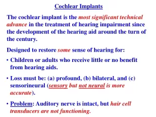
Cochlear Implants • Medical devices that bypass damaged structures in the inner ear • Stimulate directly auditory nerve to allow deaf individuals to learn to hear and interpret sounds and speech • For patients who have an injury at the cilium level in the cochlea
Cochlear Implants • Electrodes formed from a bundle of wires • Fed into the snail-shaped cochlea of the inner ear • Different auditory nerve fibers are stimulated at different places in the cochlea • Different electrodes are stimulated depending on the frequency of the signal
WIMS Cochlear Implant • WIMS • Development of cochlear implant based on thin-film electrodes • Direct stimulation of the auditory nerve • Cochlear Implant design • Allow a simpler insertion for surgeons • Minimize damage to healthy ear tissue • Current implants • Anywhere from 16 to 22 stimulating sites along its length • WIMS implant • Expected host up to 128 stimulating sites
UPRM Work • University of Puerto Rico at Mayagüez • Development of software for the microcontroller developed by WIMS • WIMS Board is under development • Testing Methods • Demos • Tone Demo • DSP Demo
UPRM Work • WIMS Board is still under development. • Code needs to be tested. • We will demonstrate the functionality of the implant using two demonstrations • Tone Demo • Demonstrate input and output of the system • DSP Demo • Demonstrate processing in the system
Demos: Tone Demo Processor Transmitter Telemetry Chip Microcontroller Array Electronics Array RF 8-bits (ampl & freq) 16-bits (ampl & address) • Goal • Show site addressing and current amplitude by driving the appropriate LEDs represented on a graphical interface
Demos: Tone Demo • WIMS board emulated in SiLabs 8051 board • Modules • Telemetry Chip • Tone Demo C Code • LabVIEW Intefaces • Piano Demo • LED Array • Hybrid Chip Simulation
Demos: Tone Demo • LabVIEW Interface I – Piano Demo • Sends Amplitude and Frequency • Command Words • Sound generation • Individual Keys • Close Encounter Buttons • LED Array Output Control
Demos: Tone Demo LabVIEW Interface: Led Array • Get Processed Data • Simulate Hybrid Chip • Shows a representation of the electrode stimuli • Display biphasic signal
Demos: DSP Demo • DSP • Specialized microprocessor designed for Signal processing algorithms • Reduced power consumption and space requirements of the system • WIMS DSP • Fully integrated, low power DSP core • Performs Continuous Interleaved Sampling (CIS algorithm)
Demos: DSP Demo • Functionality • The WIMS DSP receives data from the chip’s analog to digital converter • Signal is compressed reducing it’s dynamic range • Sends the processed signal to the hybrid chip • Stimulates Electrodes. • By stimulating one electrode at the time • Allows better speech spectrum and speech understanding
Demos: DSP Demo • CIS Algorithm Block Diagram • Implemented in hardware in the DSP of the WIMS Microcontroller
Demos: DSP Demo Equations used for the sound filtering.
Demos: DSP Demo • Goal • Implementation of an emulator for digital signal processor of the WIMS microcontroller • System Behavior • Signals from LabVIEW interface sent throught ADC • Data Processed by emulator • Processed Data is sent to LED Array interface
Demos: DSP Demo • DSP must be initialized • ADC receives analog input. • 16-bit command word generated . • Command word sent to Hybrid Chip Lab VIEW interface to simulate electrode stimulation.
Demos: DSP Demo • Process • Receive data from the ADC • Filters this signal • Process using the CIS algorithm • Send a calculated signal containing the amplitude and channel thru the SPI • Signal goes to the Hybrid Chip • Creation of stimuli for the electrodes inside the cochlea
Description The interface named values.vi is used to send the coefficients values to the MCU. Coefficients – values that are used to initialize the DSP. LabVIEW Interface I: DSP Demo
LabVIEW Interface I: DSP Demo • Tasks • Send coefficients values to MCU’s USART through the Data Acquisition Board. • Data to be sent in the same format used in the WIMS Telemetry Chip. • Synchronize the interface with the microcontroller's USART • Guarantee data is being transmitted and received correctly. • Test interface functionality
LabVIEW Interface II: DSP Demo • WDEMO INTERFACE • Open • Preview • Convert • Analyze • Graph
LabVIEW Interface II: DSP Demo • Works in conjunction with Matlab • Out.wav File • Datastream.txt File • If Analyzed the data is displayed. • Data can also be plotted on the interface. • Goal • Work with DAQ and ADC • Communicate with MCU
Final Results • Bidirectional Communication • PC generates data • MCU process the data • PC displays output • Data Recovery Among Interfaces
Acknowledgements • Nayda Santiago, Ph. D. • David Ortiz, M.S. Student UPRM • Jamie Hetke, System Integrator • Eric Marsman, Ph.D. Student UMich • Amir Sodagar, Ph. D. • Ken Wise, Ph. D.
References • Craig Steinger-Online 8051/8052 Microcontroller Tutorial: Architecture, Assembly Language, and Hardware Interfacing • Eric D. Marsman, A DSP Architecture for Cochlear Implants; • 8051 Data sheets