1.4 Hardware Review
This document explores critical aspects of CPU architecture, including the fetch-decode-execute cycle, core distinctions between MIPS and Intel IA, and the role of registers such as PC, SP, and PSW. It highlights process protection, context switching, and the importance of device drivers in managing I/O devices. Furthermore, it discusses methods of performing I/O using interrupts and DMA, as well as the role of buses in electrical connectivity. Finally, it covers the boot process initiated by the BIOS and its subsequent checks and executions.

1.4 Hardware Review
E N D
Presentation Transcript
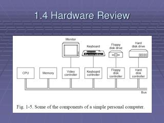
CPU • Fetch-decode-execute cycle • MIPS IA is different from Intel IA • Registers • PC • SP • PSW (EFLAGS) • What mode are we in? • Result of last operation (N,Z,V,C)
System call = way of obtaining services of OS • Often implemented via TRAP instruction
memory • Disks: sector, intersector gap, track, cylinder • ROM – nonvolatile; EEPROM or flash RAM • CMOS – low power, volatile RAM • Backed up by battery • Date/time storage, boot parameters
Multiple programs in RAM • Why? Better use of resource, multiple programs running, etc. • Needs: • Protect processes (and kernel) from each other • Handle relocation
Multiple programs in RAM • How? • Assume all programs start at virtual address 0 • Use base and limit registers • Virtual-to-physical address translation via MMU • managed by OS • Context switch – switching from 1 program to another
I/O devices • Device driver = software that talks to a controller, giving it commands and accepting responses • Must be loaded into kernel via one of the following: • Relink kernel and reboot (Unix) • Make an entry into system file & check & load entries at boot time (Windows) • Dynamically loaded drivers (USB & IEEE 1394)
Methods of communicating w/ device registers: • Use special IN/OUT instructions • Map device registers into memory (RAM) • Methods of performing I/O: • Busy waiting • Interrupts • Interrupts w/ DMA
Busy waiting • User system call driver procedure call wait (polling) return results & status • Interrupts • User system call driver procedure call w/ ISR specified • User waits but CPU is free to do something else • ISR is called only when work needs to be accomplished (and performs the work) • Interrupts w/ DMA
Servicing interrupts • I/O device has completed operation; CPU is signalled (electrically) • CPU may or may not decide to service interrupt right now • Service: • Push PC & PSW on stack • Switch to kernel mode • User interrupt vector (table) for service routine address • Restore PC & PSW and resume what was being performed • Remember: interrupts can occur at any (the worst) time so they can be disabled (ignored, queued, and/or prioritized)
Buses • Standard electrical connectivity w/ system/CPU • Ex. PCI, SCSI, USB, IEEE 1394, IDE, EIDE, ISA, ATA, SATA, AGP, cache, memory • ISA – 8.3 MHz – 16.7 MB/s • PCI – 66 MHz – 528 MB/s • USB – 1.5 MB/s • IEEE 1394 – 50 MB/s • SCSI – 160 MB/s
Boot process • Execution starts w/ code in BIOS (flash RAM or ROM) • Determine amount of memory • Scans ISA & PCI for devices and checks keyboard • Checks CMOS for boot device • First sector of boot device is read into memory and executed