Download

1 / 15
150 likes | 263 Views
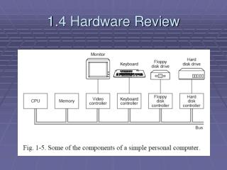
Explore the fundamentals of computer hardware components like CPUs, registers, RAM, ROM, and I/O devices. Learn about the fetch-decode-execute cycle, system calls, disk organization, and the boot process. Discover the significance of buses, interrupts, and the methods of I/O operations.

E N D
CPU • Fetch-decode-execute cycle • Fetch • Bump PC • Decode • Determine operand addr (if necessary) • Fetch operand from memory (if necessary) • Execute • Go to step 1 • MIPS IA is different from Intel IA • Registers • PC • SP • PSW (EFLAGS) • What mode are we in? • Result of last operation (N,Z,V,C)
System call = way of obtaining services of OS • Often implemented via TRAP instruction
memory • RAM • ROM – nonvolatile • EEPROM or flash RAM • CMOS – low power, volatile RAM • Backed up by battery • Date/time storage, boot parameters
Disk organization • Disks: sector, intersector gap, track, cylinder
Multiple programs in RAM • Why? Better use of resource, multiple programs running, etc. • Needs: • Protect processes (and kernel) from each other • Handle relocation
Multiple programs in RAM • How? • Assume all programs start at virtual address 0 • Use base and limit registers • Virtual-to-physical address translation via MMU • managed by OS • Context switch – switching from 1 program to another
I/O devices • Device driver = software that talks to a controller, giving it commands and accepting responses • Must be loaded into kernel via one of the following: • Relink kernel and reboot (Unix) • Make an entry into system file & check & load entries at boot time (Windows) • Dynamically loaded drivers (USB & IEEE 1394)
Methods of communicating w/ device registers: • Use special IN/OUT instructions • Map device registers into memory (RAM) • Methods of performing I/O: • Busy waiting • Interrupts • Interrupts w/ DMA
Busy waiting • User system call driver procedure call wait (polling) return results & status • Interrupts • User system call driver procedure call w/ ISR specified • User waits but CPU is free to do something else • ISR is called only when work needs to be accomplished (and performs the work) • Interrupts w/ DMA
Servicing interrupts • I/O device has completed operation; CPU is signalled (electrically) • CPU may or may not decide to service interrupt right now • Service: • Push PC & PSW on stack • Switch to kernel mode • User interrupt vector (table) for service routine address • Restore PC & PSW and resume what was being performed • Remember: interrupts can occur at any (the worst) time so they can be disabled (ignored, queued, and/or prioritized)
Buses Standard electrical connectivity w/ system/CPU (ex. PCI, SCSI, USB, IEEE 1394, IDE, EIDE, ISA, ATA, SATA, AGP, cache, memory) • AGP 3.5 - 2.1 GB/s • ATA - 33 to 133 MB/s • FireWire IEEE 1394b - 800 MB/s • ISA - 16.7 MB/s (8.3 MHz) • PCI - 528 MB/s (66 MHz) • SCSI Ultra-640 - 640 MB/s • USB3 - 4 GB/s
Boot process • Execution starts w/ code in BIOS (flash RAM or ROM) • Determine amount of memory • Scans ISA & PCI for devices and checks keyboard • Checks CMOS for boot device • First sector of boot device is read into memory and executed