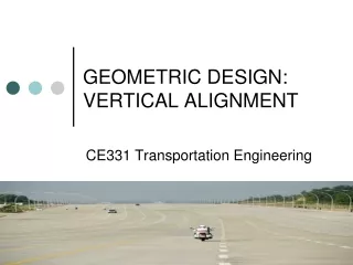
Vertical Alignment
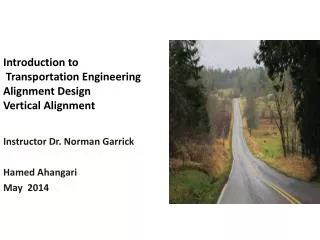
Vertical Alignment. See: http://www.fhwa.dot.gov/environment/flex/ch05.htm (Chapter 5 from FHWA’s Flexibility in Highway Design). Coordination of Vertical and Horizontal Alignment. Curvature and grade should be in proper balance Avoid Excessive curvature to achieve flat grades


Vertical Alignment
E N D
Presentation Transcript
Vertical Alignment See: http://www.fhwa.dot.gov/environment/flex/ch05.htm (Chapter 5 from FHWA’s Flexibility in Highway Design)
Coordination of Vertical and Horizontal Alignment • Curvature and grade should be in proper balance • Avoid • Excessive curvature to achieve flat grades • Excessive grades to achieve flat curvature • Vertical curvature should be coordinated with horizontal • Sharp horizontal curvature should not be introduced at or near the top of a pronounced crest vertical curve • Drivers may not perceive change in horizontal alignment esp. at night Image source: http://www.webs1.uidaho.edu/niatt_labmanual/Chapters/geometricdesign/theoryandconcepts/DescendingGrades.htm Source: A Policy on Geometric Design of Highways and Streets (The Green Book). Washington, DC. American Association of State Highway and Transportation Officials, 2001 4th Ed. P. 284
Coordination of Vertical and Horizontal Alignment • Sharp horizontal curvature should not be introduced near bottom of steep grade near the low point of a pronounced sag vertical curve • Horizontal curves appear distorted • Vehicle speeds (esp. trucks) are highest at the bottom of a sag vertical curve • Can result in erratic motion Source: A Policy on Geometric Design of Highways and Streets (The Green Book). Washington, DC. American Association of State Highway and Transportation Officials, 2001 4th Ed.
Coordination of Vertical and Horizontal Alignment • On two-lane roads when passing is allowed, need to consider provision of passing lanes • Difficult to accommodate with certain arrangements of horizontal and vertical curvature • need long tangent sections to assure sufficient passing sight distance Source: A Policy on Geometric Design of Highways and Streets (The Green Book). Washington, DC. American Association of State Highway and Transportation Officials, 2001 4th Ed.
Coordination of Vertical and Horizontal Alignment • At intersections where sight distance needs to be accommodated, both horizontal and vertical curves should be as flat as practical • In residential areas, alignment should minimize nuisance to neighborhood • Depressed highways are less visible • Depressed highways produce less noise • Horizontal alignments can increase the buffer zone between roadway and cluster of homes Source: A Policy on Geometric Design of Highways and Streets (The Green Book). Washington, DC. American Association of State Highway and Transportation Officials, 2001 4th Ed.
Coordination of Vertical and Horizontal Alignment • When possible alignment should enhance scenic views of the natural and manmade environment • Highway should lead into not away from outstanding views • Fall towards features of interest at low elevation • Rise towards features best seen from below or in silhouette against the sky Source: A Policy on Geometric Design of Highways and Streets (The Green Book). Washington, DC. American Association of State Highway and Transportation Officials, 2001 4th Ed.
Coordination of Horizontal and Vertical Alignment • Coordination of horizontal and vertical alignment should begin with preliminary design • Easier to make adjustments at this stage • Designer should study long, continuous stretches of highway in both plan and profile and visualize the whole in three dimensions (FHWA, Chapter 5)
Coordination of Horizontal and Vertical Alignment Source: FHWA, Chapter 5
Coordination of Horizontal and Vertical Alignment • Should be consistent with the topography • Preserve developed properties along the road • Incorporate community values • Follow natural contours of the land Source: FHWA, Chapter 5
Good Coordination of Horizontal and Vertical Alignment • Does not affect aesthetic, scenic, historic, and cultural resources along the way • Enhances attractive scenic views • Rivers • Rock formations • Parks • Historic sites • Outstanding buildings Source: FHWA, Chapter 5
Source: A Policy on Geometric Design of Highways and Streets (The Green Book). Washington, DC. American Association of State Highway and Transportation Officials, 2001 4th Ed.
Source: A Policy on Geometric Design of Highways and Streets (The Green Book). Washington, DC. American Association of State Highway and Transportation Officials, 2001 4th Ed.
There are 2 problems with this alignment. What are they? There are 2 problems with this alignment. What are they? Source: A Policy on Geometric Design of Highways and Streets (The Green Book). Washington, DC. American Association of State Highway and Transportation Officials, 2001 4th Ed.
Source: A Policy on Geometric Design of Highways and Streets (The Green Book). Washington, DC. American Association of State Highway and Transportation Officials, 2001 4th Ed.
Source: A Policy on Geometric Design of Highways and Streets (The Green Book). Washington, DC. American Association of State Highway and Transportation Officials, 2001 4th Ed.
Source: A Policy on Geometric Design of Highways and Streets (The Green Book). Washington, DC. American Association of State Highway and Transportation Officials, 2001 4th Ed. Maybe we want this if we are trying to slow people down???
Source: A Policy on Geometric Design of Highways and Streets (The Green Book). Washington, DC. American Association of State Highway and Transportation Officials, 2001 4th Ed.
Source: A Policy on Geometric Design of Highways and Streets (The Green Book). Washington, DC. American Association of State Highway and Transportation Officials, 2001 4th Ed.
Source: A Policy on Geometric Design of Highways and Streets (The Green Book). Washington, DC. American Association of State Highway and Transportation Officials, 2001 4th Ed.
Source: A Policy on Geometric Design of Highways and Streets (The Green Book). Washington, DC. American Association of State Highway and Transportation Officials, 2001 4th Ed.
Source: A Policy on Geometric Design of Highways and Streets (The Green Book). Washington, DC. American Association of State Highway and Transportation Officials, 2001 4th Ed.
Source: A Policy on Geometric Design of Highways and Streets (The Green Book). Washington, DC. American Association of State Highway and Transportation Officials, 2001 4th Ed.
A B Source: A Policy on Geometric Design of Highways and Streets (The Green Book). Washington, DC. American Association of State Highway and Transportation Officials, 2001 4th Ed.
Source: A Policy on Geometric Design of Highways and Streets (The Green Book). Washington, DC. American Association of State Highway and Transportation Officials, 2001 4th Ed.
Source: A Policy on Geometric Design of Highways and Streets (The Green Book). Washington, DC. American Association of State Highway and Transportation Officials, 2001 4th Ed.
Vertical Alignment Equations
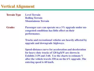
Curve/grade tradeoff • a 3% grade causes a reduction in speed of 10 mph after 1400 feet
Vertical Alignment - General • Parabolic shape • VPI, VPC, VPT, +/- grade, L • Types of crest and sag curves – see Exhibit 3-73 p. 269 Source: A Policy on Geometric Design of Highways and Streets (The Green Book). Washington, DC. American Association of State Highway and Transportation Officials, 2001 4th Ed.
Vertical Alignment – General (Cont.) • Crest – stopping, or passing sight distance controls • Sag – headlight/SSD distance, comfort, drainage and appearance control • Green Book vertical curves defined by K = L/A = length of vertical curve/difference in grades (in percent) = length to change one percent in grade
Vertical Alignment - General Parabolic shape as applied to vertical curves y = ax2 + bx + c Where: y = roadway elevation at distance x x = distance from beginnning of vertical curve a, b = coefficients that define shape c = elevation of PVC
Vertical Alignment - General Parabolic shape as applied to vertical curves a = G2 – G1 L b = G1 Source: A Policy on Geometric Design of Highways and Streets (The Green Book). Washington, DC. American Association of State Highway and Transportation Officials, 2001 4th Ed.
Vertical Curve AASHTO Controls (Crest) • Based on stopping sight distance • Minimum length must provide sight distance S • Two situations (Crest, assumes 3.5 and 2.0 ft. heights) Source: Transportation Engineering On-line Lab Manual, http://www.its.uidaho.edu/niatt_labmanual/
Assistant with Target Rod (2ft object height) Observer with Sighting Rod (3.5 ft)
Vertical Curve AASHTO Controls (Crest) Source: A Policy on Geometric Design of Highways and Streets (The Green Book). Washington, DC. American Association of State Highway and Transportation Officials, 2001 4th Ed. Note: for passing site distance, use 2800 instead of 2158
Example: Assume SSD < L, Design speed is 60 mph G1 = 3% and G2 = -1%, what is L? SSD = 525 feet Lmin = |(-3 - 1)| (525 ft)2 = 510.9 ft 2158 S > L, so try other equation
Example: Next try SSD > L, Design speed is 60 mph G1 = 3% and G2 = -1%, what is L? SSD = 525 feet Lmin = 2 (525’) – 2158’ = 510.5’ S > L, so equation works |(-3 - 1)|
Can also use K = L / A Where K = length of curve per percent algebraic difference in intersecting grade Charts from Green Book
Vertical Curve AASHTO Controls (Crest) Since you do not at first know L, try one of these equations and compare to requirement, or use L = KA (see tables and graphs in Green Book for a given A and design speed) Note min. L(ft) = 3V(mph) – Why?
Sag Vertical Curves • Sight distance is governed by nighttime conditions • Distance of curve illuminated by headlights need to be considered • Driver comfort • Drainage • General appearance
Vertical Curve AASHTO Controls (Sag) Headlight Illumination sight distance with S < L S < L L = AS2 S > L L = 2S – (400 + 3.5S) A Headlight Illumination sight distance with S > L Source: A Policy on Geometric Design of Highways and Streets (The Green Book). Washington, DC. American Association of State Highway and Transportation Officials, 2001 4th Ed. 400 + (3.5 * S)
Vertical Curve AASHTO Controls (Sag) • For driver comfort use: L = AV2 46.5 (limits g force to 1 fps/s) • To consider general appearance use: L = 100 A Source: A Policy on Geometric Design of Highways and Streets (The Green Book). Washington, DC. American Association of State Highway and Transportation Officials, 2001 4th Ed.
Sag Vertical Curve: Example A sag vertical curve is to be designed to join a –3% to a +3% grade. Design speed is 40 mph. What is L? Skipping steps: SSD = 313.67 feet S > L Determine whether S<L or S>L L = 2(313.67 ft) – (400 + 2.5 x 313.67) = 377.70 ft [3 – (-3)] 313.67 < 377.70, so condition does not apply
Sag Vertical Curve: Example A sag vertical curve is to be designed to join a –3% to a +3% grade. Design speed is 40 mph. What is L? Skipping steps: SSD = 313.67 feet L = 6 x (313.67 ft)2 = 394.12 ft 400 + 3.5 x 313.67 ft 313.67 < 394.12, so condition applies
Sag Vertical Curve: Example A sag vertical curve is to be designed to join a –3% to a +3% grade. Design speed is 40 mph. What is L? Skipping steps: SSD = 313.67 feet Testing for comfort: L = AV2 = (6 x [40 mph]2) = 206.5 feet 46.5 46.5
Sag Vertical Curve: Example A sag vertical curve is to be designed to join a –3% to a +3% grade. Design speed is 40 mph. What is L? Skipping steps: SSD = 313.67 feet Testing for appearance: L = 100A = (100 x 6) = 600 feet
Vertical Curve AASHTO Controls (Sag) • For curb drainage, want minimum of 0.3 percent grade within 50’ of low point = need Kmax = 167 (US units) • For appearance on high-type roads, use minimum design speed of 50 mph (K = 100) • As in crest, use minimum L = 3V
Other important issues: • Use lighting if need to use shorter L than headlight requirements • Sight distance at under crossings
Example: A crest vertical curve joins a +3% and –4% grade. Design speed is 75 mph. Length = 2184.0 ft. Station at PVI is 345+ 60.00, elevation at PVI = 250 feet. Find elevations and station for PVC and PVT. L/2 = 1092.0 ft Station at PVC = [345 + 60.00] - [10 + 92.00] = 334 + 68.00 Distance to PVC: 0.03 x (2184/2) = 32.76 feet ElevationPVC = 250 – 32.76 = 217.24 feet Station at PVT = [345 + 60.00] + [10 + 92.00] = 357 + 52.00 Distance (vertical) to PVT = 0.04 x (2184/2) = 43.68 feet Elevation PVT = 250 – 43.68 = 206.32 feet