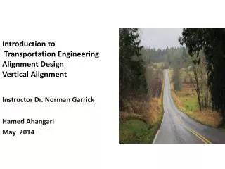
Introduction to Transportation Engineering Alignment Design Vertical Alignment
Introduction to Transportation Engineering Alignment Design Vertical Alignment. Instructor Dr. Norman Garrick Hamed Ahangari May 2014. Basic Elements. Horizontal Alignment Vertical Design Cross Section. Horizontal Alignment. Vertical Alignment. Crest Curve. G 2. G 3. G 1.

Introduction to Transportation Engineering Alignment Design Vertical Alignment
E N D
Presentation Transcript
Introduction to Transportation EngineeringAlignment DesignVertical Alignment Instructor Dr. Norman Garrick Hamed Ahangari May 2014
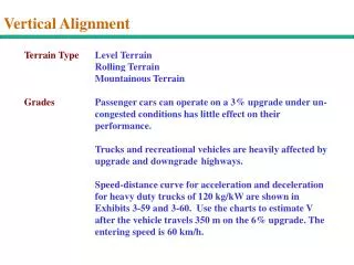
Basic Elements • Horizontal Alignment • Vertical Design • Cross Section
Horizontal Alignment Vertical Alignment Crest Curve G2 G3 G1 Sag Curve
Parabolic Curve BVC G1 G2 EVC PI L/2 L/2 L Change in grade: A = G2 - G1G is expressed as % Rate of change of curvature: K = L / |A| Rate of change of grade: r = (g2 - g1) / L Equation for determining the elevation at any point on the curve y = y0 + g1x + 1/2 rx2 where, y0 = elevation at the BVCg = grade expressed as a ratio x= horizontal distance from BVC r = rate of change of grade (ratio)
El. 200 B 190 180 170 160 150 140 130 A ` El. 100 120 110
Alignment Standard related to Design Speed Site Engineering by Steven Storm
El. 200 B 190 180 170 160 150 140 130 A ` El. 100 120 110
11+50 11+00 El. 200 B 190 8+00 7+00 9+00 6+00 10+00 180 5+00 4+00 170 3+00 160 2+00 150 1+00 140 130 A 0+00 ` 120 110
Longitude Profile Elevation 200 B (1150,200) 180 160 140 120 100 A (0,100) Distance 100 200 300 400 500 600 700 800 900 1000 1100
Elevation 200 B (1150,200) 180 G3=9.3% h=40’,d=430’ 160 G2=6.25% h=20’,d=320’ 140 G1=10% 120 h=40’,d=400’ 100 A (0,100) Distance 100 200 300 400 500 600 700 800 900 1000 1100
Elevation 200 B (1150,200) 180 G3=9.3% 160 G2=6.25% 140 G1=10% 120 100 A (0,100) Distance 100 200 300 400 500 600 700 800 900 1000 1100
Vertical alignment • Step 1: First provide the longitude profile of the road which contain earth elevations. • Step 2: Based on the maximum allowable slope and topographic condition, determine vertical tangents. • Step 3: Calculate the parabolic vertical curve specifications.
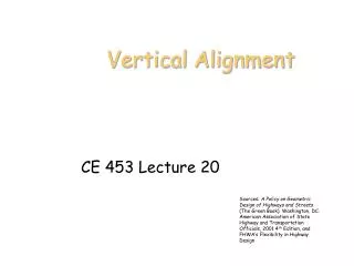
Example We want to design a road which connect point A and B • Design Speed is 30 mph • Provide vertical alignment for this road
` B A