Download
1 / 26
260 likes | 380 Views
Optical Springs at the 40m QND Workshop, Hannover Dec 14, 2005 Robert Ward for the 40m Team

E N D
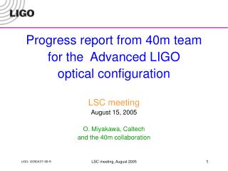
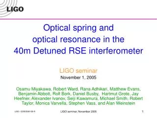
Optical Springs at the 40m QND Workshop, Hannover Dec 14, 2005 Robert Ward for the 40m Team Osamu Miyakawa, Rana Adhikari, Matthew Evans, Benjamin Abbott, Rolf Bork, Daniel Busby, Hartmut Grote, Jay Heefner, Alexander Ivanov, Seiji Kawamura, Michael Smith, Robert Taylor, Monica Varvella, Stephen Vass, and Alan Weinstein Optical Springs at the 40m
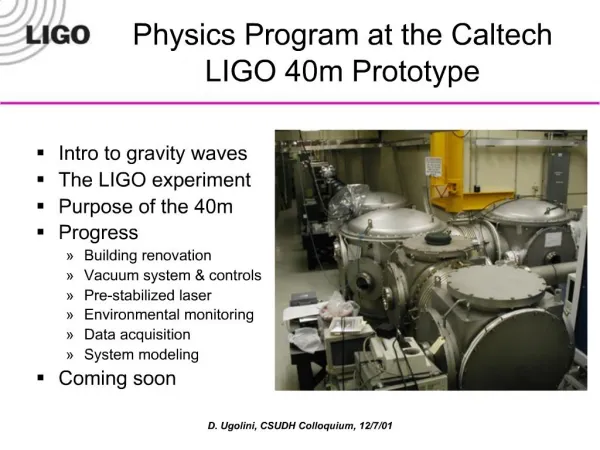
Caltech 40 meter prototype interferometer An interferometer as close as possible to the Advanced LIGO optical configuration and control system • Detuned Resonant Sideband Extraction (DRSE) • Power Recycling • Suspended mass • Single pendula • Digital controls system • Same cavity finesse as AdLIGO baseline design • 100x shorter storage times. Optical Springs at the 40m
Carrier (Resonant on arms) -f2 -f1 f1 f2 AdLIGO signal extraction scheme ETMy • Mach-Zehnder will be installed to eliminate sidebands of sidebands. • Only + f2is resonant on SRC. • Unbalanced sidebands of +/-f2 due to detuned SRC produce good error signal for Central part. • Arm cavity signals are extracted from beat between carrier and f1 or f2. • Central part (Michelson, PRC, SRC) signals are extracted from beat between f1 and f2, not including arm cavity information. 4km f2 ITMy ETMx PRM ITMx BS 4km f1 SRM Single demodulation Arm information Double demodulation Central part information Optical Springs at the 40m
The Story So Far To understand why we saw the optical springs in the way we have, it helps to know the story of Lock Acquisition at the 40m. Optical Springs at the 40m
40m Lock Acquisition part I: Off-resonant lock scheme for a single cavity Transmitted light is used as Resonant Lock Off-resonant Lock point Optical Springs at the 40m
40m Lock acquisition procedure Start with no DOFs controlled, all optics aligned. ITMy 166MHz ITMx 13m MC BS 33MHz PRM PO DDM SP33 SRM SP166 SP DDM AP166 AP DDM Optical Springs at the 40m
1/sqrt(TrY) 40m Lock acquisition procedure DRMI + 2arms with offset Average wait : 3 minute (at night, with tickler) ITMy 166MHz ITMx 13m MC 1/sqrt(TrX) BS 33MHz PRM T=7% PO DDM SRM SP166 SP33 T=7% I SP DDM Q AP166 AP DDM Optical Springs at the 40m
-1 40m Lock acquisition procedure Short DOFs -> DDM DARM -> RF signal CARM -> DC signal 1/sqrt(TrX)+ 1/sqrt( TrY) CARM -> Digital CM_MCL servo CARM + + Alternative path DARM ITMy 166MHz ITMx 13m MC BS 33MHz PRM PO DDM SRM SP33 SP166 SP DDM To DARM AP166 AP DDM AP166 / (TrX+TrY) Optical Springs at the 40m
-1 40m Lock acquisition procedure Reduce CARM offset: 1. Go to higher ARM power 2. Switch on AC-coupled analog CM_AO servo, using REFL DC as error signal. 3. Switch to RF error signal (POX) at half-max power. 4. Reduce offset/increase gain of CM_AO. DARM ITMy 166MHz GPR=5 ITMx 13m MC BS SP166 33MHz PRM PO DDM SRM SP33 SP DDM 5. Packup MOPA and send it to LLO for S5 To DARM REFL AP166 AP DDM AP166 / (TrX+TrY) Optical Springs at the 40m
Optical spring in detuned RSE Optical spring in detuned RSE was first predicted using two-photon formalism. h a :input vacuum b :output D : M : h :strain hSQL:standard quantum limit t: transmissivity of SRM k: coupling constant F: GW sideband phase shift in SRC b: GW sideband phase shift in IFO h D laser Signal recycling mirror b a z: homodyne phase A. Buonanno, Y.Chen, Phys. Rev. D 64, 042006 (2001) Optical Springs at the 40m
SRC DARM Detune Cartoon IFO DARM/CARM IFO Differential Arm mode is detuned from resonance at operating point FWHM Carrier frequency Sideband amplitude [a.u.] slope related to spring constant? fsig IFO Common Arm mode is detuned from resonance at intial locking point LSB USB frequency offset from carrier [Hz] • Responses of GW USB and GW LSB are different due to the detuning of the signal recycling cavity. PRC CARM Optical Springs at the 40m
DARM TFs as CARM offset is reduced Optical Springs at the 40m
CARM optical springs Solid lines are from TCST Stars are 40m data Max Arm Power is ~80 Also saw CARM anti-springs, but don’t have that data Optical Springs at the 40m
Optical spring and Optical resonance in differential arm mode of detuned RSE • Optical gain of L- loop DARM_IN1/DARM_OUT divided by pendulum transfer function • Optical spring and optical resonance of detuned RSE were measured. • Frequency of optical spring depends on cavity power, mass, detuning phase of SRC. • Frequency of optical resonance depends on detuning phase of SRC. • Theoretical line was calculated using A. Buonanno and Y.Chen’s equations. Optical Springs at the 40m
Positive spring constant SRM is locked at opposite position from anti-resonant carrier point(BRSE). Optical spring disappeared due to positive spring constant. Broadband SR Broadband RSE Optical Springs at the 40m
Simple picture of optical spring in detuned RSE Let’s move arm differentially, X arm longer, Y arm shorter from full RSE Wrong SRM position Correct SRM position BRSE X arm Y arm Y arm X arm Power(W) Power(W) Power(W) DARM (Lx-Ly) DARM (Lx-Ly) DARM (Lx-Ly) • Power X arm down, Y arm up X arm down, Y arm down X arm up, Y arm down • Radiation pressure X arm down, Y arm up X arm down, Y arm down X arm up, Y arm down • Spring constant Negative(optical spring) N/A Positive(no optical spring) Optical Springs at the 40m
Relationship between the CARM and DARM springs at the 40m • With the 40m Lock Acquisition scheme, we only see a CARM spring if there’s also a DARM spring. • Details tomorrow Using the DC-locking scheme for the arms, there are, prima facie, four locking points corresponding to the four possible gain combinations, but only two will acquire lock. Correct SRM position Incorrect SRM position Optical Springs at the 40m
Will it lock? • x-axis: EY position • y-axis: signal • blue:X err • green: Y err • black: DARM • red: CARM modeled with FINESSE NO YES Optical Springs at the 40m
DRMI lock using double demodulation with unbalanced RF sideband in SRC Carrier Carrier 33MHz 166MHz ITMy ITMx BS Unbalanced 166MHz PRM DDM PD 33MHz Belongs to next carrier Belongs to next carrier SRM DDM PD OSA DDM PD OSA Belongs to next carrier Optical Springs at the 40m
b2 demodulation phase b1 Unbalanced Sideband Detection • Kentaro Somiya “Photodetection method using unbalanced sidebands for squeezed quantum noise in a gravitational wave interferometer” PHYSICAL REVIEW D67,122001 2003 • A. Buonanno, Y. Chen, N. Mavalvala, “Quantum noise in laser-interferometer gravitational-wave detectors with a heterodyne readout scheme” PHYSICAL REVIEW D 67,122005 2003 • Can not be used to circumvent the standard quantum limit, due to heterodyne noise • Can be used to change the measurement quadrature, and thus reshape the GW response +166MHz sideband Optical Springs at the 40m
Changing the DARM quadrature Story: • Lock IFO with CARM offset • Handoff DARM to RF • Adjust RF demodulation phase • Reduce CARM offset • This changes the quadrature of the signal. As we are not compensating for this by adjusting the demod phase, the shape of the response changes. May also be some overall gain change due to imperfect normalization Optical Springs at the 40m
Optickle Results GW response in a single, chosen quadrature at multiple CARM offsets Optical Springs at the 40m
Why is the correct SRM position harder to lock? • The correctly detuned SRC doesn’t lock as easily as the oppositely tuned SRC • True for both full IFO and just the DRMI (though less noticeable on DRMI) • For full IFO, lock time goes from 1 to 5 minutes. • Have we just not tuned-it-up it right yet? Optical Springs at the 40m
Mode healing/injuring at Dark Port Negative spring constant with optical spring Positive spring constant with no optical spring Carrier power at DP is 10x smaller Repeatable The same alignment quality Optical Springs at the 40m
Compensating the resonances UGFs ~ 250Hz Compensation Filters for the various resonances: Optical Opto-mechanical DARM CARM Optical Springs at the 40m
DARM loop: Calibration questions S C D DARM_IN1 Cavity response Sensing DARM EXC DARM_IN2 P pendulum Use DARM_IN1 • Measure DARM_IN2/EXC= • Estimate S • Measure (or estimate) C Use DARM_OUT • Measure DARM_IN1/EXC= • Estimate A • Estimate P A Feedback filter Actuator F DARM_OUT Optical Springs at the 40m