Download
1 / 15
150 likes | 323 Views
DC Readout Experiment at the Caltech 40m Laboratory Robert Ward Caltech Amaldi 7 July 14 th , 2007 the 40m team:

E N D
DC Readout Experiment at the Caltech 40m Laboratory Robert Ward Caltech Amaldi 7 July 14th, 2007 the 40m team: Rana Adhikari, Benjamin Abbott, Rich Abbott, Rolf Bork, Darcy Barron, Tobin Fricke, Valery Frolov, Jay Heefner, Alexander Ivanov, Osamu Miyakawa, Kirk McKenzie, Royal Reinecke, Bram Slagmolen, Michael Smith, Bob Taylor, Stephen Vass, Sam Waldman, and Alan Weinstein R. Ward, Caltech
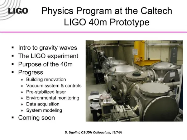
Caltech 40 meter prototype interferometer(mini-LIGO) The Mission: • Prototype the Advanced LIGO Length and Alignment Controls • Develop DC readout scheme • DC Readout is the baseline GW signal extraction technique for eLIGO & aLIGO • Characterize noise mechanisms • Gain confidence in modeling • Testbed for AdLIGOcontrols technologies • Training ground Prototyping will yield crucial information about how to build and run AdLIGO (and eLIGO). R. Ward, Caltech
Prototyping for eLIGO: Power Recycled Fabry Perot Michelson Fully instrumented prototype Initial LIGO-style single pendulums, passive seismic stacks Initial LIGO digital control system, interfaced with aLIGO style subsystem for DC Readout OMC length and alignment controlled digitally via dither locking ETMy 40m ITMy 13m MC BS SP166 ITMx PRM ETMx SRM DARM DC SP 33 REFL AP 33 OMC DARM RF R. Ward, Caltech
AS Power No slope Some linear component DARM (L-) Gravitational Wave Signal Extraction:RF and DC Readout RF Readout At the dark fringe, the asymmetric port power is quadratic in DARM—so we must use RF sidebands as a local oscillator to get a signal proportional to DARM (GW strain). carrier from arms DARM motion rotates arm fields Q phase RF sideband (local oscillator) non-zero projection zero projection DC Readout Offset the differential arm degree of freedom (DARM) slightly from the dark fringe. Asymmetric port power is now proportional to GW strain. No more RF sidebands. lock to this level R. Ward, Caltech
Why DC Readout? • DC Readout can have lower shot noise • homodyne shot noise is lower than heterodyne shot noise • DC Readout can also reduce susceptibility to laser noises andtechnical noises (mainly due to the RF sidebands): • laser noise (intensity & frequency) • oscillator noise (amplitude & phase) • photodetector saturations (no more AS_I current) • effects of unstable recycling cavity: • junk light • imperfect spatial overlap of local oscillator and GW signal fields RF Sideband Field (local oscillator) GW signal field R. Ward, Caltech
Better Signal Detection:Output Mode Cleaner • OMC removes most of the junk light→no more photodetector saturations, less shot noise, and no more spatial overlap problem • DC Readout requires an in-vacuum, seismically isolated output mode cleaner and photodetector • New noise sources include OMC length and alignment noise Caltech 40m R. Ward, Caltech
Perfecting the spatial overlap:cleaning the modes AS PORT Before OMC OMC Transmitted RF local oscillator + junk light DC local oscillator + signal field signal field R. Ward, Caltech
ELECTRONICS PD MMT1 OMC Tip/Tilt RF PICKOFF MMT2 DC Readout @ Caltech 40m • Monolithic, 4-mirror output mode cleaner • finesse: 210 • 92% transmission • 4-mirrors to reduce accidental HOM resonances • Pair of PZT-driven tip/tilt steering mirrors for input to OMC • In-vacuum photodetector with electronic preamplifier • On a seismic isolation stack • Not suspended • Beam picked off before OMC for an RF sensing chain for comparisons & lock acquisition R. Ward, Caltech
Laser Intensity Noise • RF – AS_Q : AS_Q dL- * RIN + RIN * dfc / fc (rad. pres.) • DC – AS_DC is first order sensitive to AM: AS_DC RIN * ΔL- • RF – sidebands transmitted to the dark port unfiltered (only a 4 kHz MC pole) • DC – carrier filtered by the coupled PR-Arm cavity • Use the IFO to filter laser noise modeling results from Optickle R. Ward, Caltech
Laser Frequency Noise • RF – audio noise sidebands beat with the carrier contrast defect: AS_Q CD * dn • DC – arm cavity pole imbalance couples carrier frequency noise to dark port AS_DC dfc / fc • RF – sidebands transmitted to the dark port unfiltered (only a 4 kHz MC pole) • DC – carrier filtered by the coupled PR-Arm cavity R. Ward, Caltech
Oscillator Phase Noise • RF – Not completely understood. Something to do with sideband imbalance and higher order modes somewhere. • DC – Some coupling through finite finesse of OMC and maybe through aux. LSC loops (CARM, MICH, PRC). Closed loop modeling tools under development. • RF – sidebands transmitted to the dark port unfiltered (only a 4 kHz MC pole) • DC – sidebands rejected by OMC R. Ward, Caltech
Oscillator Amplitude Noise • RF – very similar to laser AM (looks like a gain modulation). • DC – can create intensity noise (oscillator steals power from the carrier) and can leak through OMC • RF – sidebands transmitted to the dark port unfiltered (only a 4 kHz MC pole) • DC – sidebands rejected by OMC R. Ward, Caltech
RF vs DC: Displacement Noise DC Readout DARM offset ~25pm seismic + control omc dither lines cal line frequency noise ? input steering + clipping? R. Ward, Caltech
Preliminary Noise Budgeting R. Ward, Caltech
coming attractions • DC Readout on a tuned-RSE 40m • A similar DC Readout system will be installed as part of Enhanced LIGO • 40m will be re-configured (optics recoated/polished, cavity lengths changed) to prototype the new aLIGO sensing scheme. tuned-RSE DARM TF Miyakawa et al, Phys. Rev. D74, 022001 (2006) R. Ward, Caltech