Download
1 / 28
290 likes | 470 Views
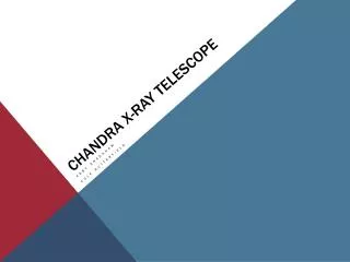
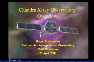
Chandra X-ray Observatory Overview. Roger Brissenden Smithsonian Astrophysical Observatory CIAO Workshop 23 April 2001. Overview. Mission Summary, Launch and Architecture Mission and Observatory Description Spacecraft Subsystems High Resolution Mirror Assembly Science Instruments

E N D
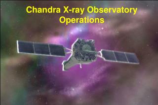
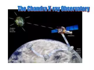
Chandra X-ray Observatory Overview Roger Brissenden Smithsonian Astrophysical Observatory CIAO Workshop 23 April 2001
Overview • Mission Summary, Launch and Architecture • Mission and Observatory Description • Spacecraft Subsystems • High Resolution Mirror Assembly • Science Instruments • Chandra X-ray Center Architecture
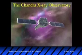
NASA Great Observatories CHANDRA
1. Chandra Mission Summary • Launch July 23, 1999 • STS-93/ Inertial Upper Stage / Integral Propulsion System • 10,000 km x 140,000 km, 28.4o Inclined Orbit • Design Lifetime > 5 Years • 10-m Focal Length Wolter -1 Mirror: 4 nested Mirror Pairs • Energy Range: 0.1-10 KeV • 2 Imaging Focal Plane Science Instruments • ACIS (Advanced CCD Imaging Spectrometer) • HRC (High Resolution Camera) • 2 Objective Transmission Gratings for Dispersive Spectroscopy • LETG (Low-Energy Transmission Grating) • HETG (High-Energy Transmission Grating)
Chandra Launch • Launched on Space Shuttle Columbia 7/23/99 on the third attempt • Shuttle placed Chandra and IUS in 150 mile orbit • Chandra was the longest and heaviest payload launched on the Shuttle • Payload bay doors open 1.5 hours after launch • Chandra/IUS deployed 7.5 hours after launch
Chandra Deployment and Orbit • Inertial Upper Stage (IUS) boosted Chandra from shuttle orbit to transfer orbit. Two stage rocket with two 2 minute burns. • Chandra separated from the IUS 9.5 hr into mission with orbit of 300km x 74,000km • Chandra’s Integral Propulsion System fired 5 times over 15 days to reach final orbit: 10,000 km x 140,000 km. Orbit of 64 hrs and going 1/3 of way to moon
Chandra Operations • Mission science plan converted to command loads and uplinked to Chandra • X-ray events collected and stored on Solid-State Recorders (SSR) • Ground contact established every ~8 hours through Deep Space Network • SSR data downlinked • new command load uplinked (up to 72 hours of stored commands) • Data transferred to OCC through JPL for science processing sssssssssssssssssssssss CXO CXC OCC
Telemetry Commands Telemetry (Via Shuttle) Commands Telemetry Deep Space Network Telemetry Commands Deep Space Network Commands DSN Scheduling State Vector OCC Off-Line System On-Line System S/C Support & Data Capture Eng Analysis Observation Request Mission Schedules Attitude Det. & Telemetry Telemetry Sensor Cal Processing Mission Planning Command Ops CXC & Scheduling Processing Simulator Command Operations Communication Proposed Observation Management Database Science Data IPIs, Guest Observers S/W Changes Flight S/W Maint Fac Chandra
3. Spacecraft Systems • Command, Control and Data Management • 2 low gain antennas, 2 S-band transponders • Two solid state recorders, each 1.8 GB • Redundant 16-bit On Board Computers (OBC), interface units, command and telemetry units, remote command and telemetry units • 32 kbps telemetry with usual 24 kbps science and 8 kbps engineering • Electrical Power • Generates, stores and distributes electrical power to the spacecraft • 2 solar wings provide 2112 watts • 3 Ni Hydride batteries capacity 120 Amp hours for eclipses • Thermal Control • Passive elements include multi-layer insulation and radiators • Active elements include thermostats and sensors • OBC controls HRMA at 70 +/- 2.5 deg with active elements
Spacecraft Subsystems • Propulsion • Integral propulsion system used for transfer orbit, deactivated • Momentum unloading propulsion system for unloading momentum from reaction wheels • Pointing Control and Attitude Determination • Sensors and control hardware to point, slew, solar array positioning and momentum unloading • Pointing requirements a modest ~30” due to photon counting nature of the science instruments • Pointing direction determined from aspect camera tracking 5-8 stars and gyroscopes • Photon positions are reconstructed using aspect camera data during ground processing • Performance of aspect system gives ~3” absolute pointing, 0.3” image reconstruction and 0.6” celestial location • System includes 6 reaction wheels for attitude control, coarse and fine sun sensors for pointing without aspect camera • Spacecraft dithered during observations with ~16 arcsec Lissajous
4. High Resolution Mirror Assembly • 4 pairs of concentric thin-walled, grazing incidence Wolter Type-I mirrors • Fabricated from Zerodur, polished to 3A and coated with Ir • Diameters range from 0.65 to 1.23m and total weight 1484 Kg • Characteristics • Focal length 10m • Plate Scale 48.8 microns/arcsec • PSF (FWHM) 0.5 arcsec • Ghost-free FOV 30’ diameter • Effective Area • @ 0.25 keV 800 cm^2 • @ 5.0 keV 400 cm^2 • @ 8.0 keV 100 cm^2
HRMA Effective Area HRMA Encircled Energy
5. Chandra Science Instruments Z+ ACIS-I • Advanced CCD Imaging Spectrometer (ACIS) • CCD array with 16’x16’ field of view (ACIS-I) • high energy grating readout array (ACIS-S) • High Resolution Camera (HRC) • microchannel plate imager with 31’x31’ field of view (HRC-I) • low energy grating readout array (HRC-S) • High Energy Transmission Grating Spectrometer (HETG) • transmission grating pairs for medium and high energy • Low Energy Transmission Grating Spectrometer (LETG) • transmission grating for low energy b b Y+ ACIS-S HRC-I HRC-S
Top Hat and Lean-to Optical Bench PSMC RCTU BTU HRC TSC ACIS FLCA ACIS Radiator Shade ACIS Sun Shade Science Instrument Module • ACIS and HRC mounted on SIM along the Z axis • SIM provides 20 inches of motion in Z to select ACIS-I, ACIS-S, HRC-I or HRC-S • Provides 0.8 inches of motion in X to adjust focus
Advanced CCD Imaging Spectrometer (ACIS) • Ten 1024x1024 pixel CCDs • 2x2 array for imaging: ACIS-I labeled I0-I3 • 1x6 array for imaging or spectroscopy: ACIS-S labeled S0-S5 • 6 chips can be operated simultaneously • Array Size 16.9x16.9 arcmin (ACIS-I), 8.3x50.6 arcmin (ACIS-S) • Pixel Size 0.49 arcsec • 8 Front-illuminated and 2 back-illuminated chips • BI chips are S1 and S3 • BI response extends lower that FI • Average energy resolution of BI chips better than FI
High Resolution Camera (HRC) • Microchannel plate device with imaging and spectroscopy detectors • Time resolution 16 microseconds • Energy Range 0.08 – 10 keV • Pixel readout size 6.4 microns = 0.13 arcsec/pix • Detection sequence for X-ray • Passes through UV-ion shield • Through photocathode yields photo emission • Photoelectrons accelerated by electric field • Pass through second microchannel plate for additional gain • Electron cloud (2e7 electrons/photon) detected with wire cross grid detector
Grating Spectrometers • HETG • Designed for use with ACIS-S providing E/delta(E) to 1000 between 0.4 and 10.0 keV • Two sets of gratings • Medium Energy Gratings (MEG) for use with outer 2 mirrors • High Energy Gratings (HEG) for use with inner 2 mirrors • Mounted at different angles to form an “X” dispersed pattern • LETG • Provides highest resolving power at low energies • Designed for use with HRC-S with 0.07 – 7.29 keV • E/delta(E) > 1000 for 0.07 < E < 0.15 keV • E/delta(E) < 1000 for E > 0.15 keV
Chandra Grating Spectrometers m=2 d Incoming Radiation m=1 m=0 m=-1 m = d sin m=-2