Download
1 / 39
390 likes | 427 Views
This text delves into the complex processes of scattering in acoustical oceanography, including reflection, refraction, and diffraction at inhomogeneous surfaces. It explores how scattering influences sound pressure distribution and reverberation in different ocean layers, from surface reverb to bottom reflections. The discussion also covers the concept of backscatter, wavelength dependency, and the interaction of incident and scattered waves around objects.

E N D
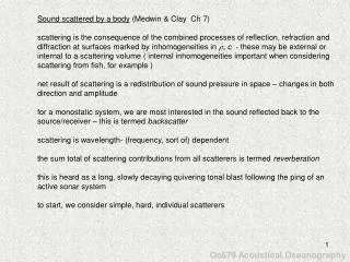
Sound scattered by a body (Medwin & Clay Ch 7) scattering is the consequence of the combined processes of reflection, refraction and diffraction at surfaces marked by inhomogeneities in , c - these may be external or internal to a scattering volume ( internal inhomogeneities important when considering scattering from fish, for example ) net result of scattering is a redistribution of sound pressure in space – changes in both direction and amplitude for a monostatic system, we are most interested in the sound reflected back to the source/receiver – this is termed backscatter scattering is wavelength- (frequency, sort of) dependent the sum total of scattering contributions from all scatterers is termed reverberation this is heard as a long, slowly decaying quivering tonal blast following the ping of an active sonar system to start, we consider simple, hard, individual scatterers Oc679 Acoustical Oceanography
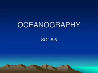
explosive source at 250 m nearby receiver at 40 m bottom depth 2000 m reverb following explosive charge initial surface reverb is sharp, followed by tail due to multiple reflection & scattering then volume reverb in mid-water column (incl. deep scattering layer) then bottom reflection, 2nd surface reflection, and long tail of bottom reverb Oc679 Acoustical Oceanography
transmission is a gated sinusoid or ping of duration tp • sound pressure scattered by a small object – crests of sinusoid indicated as a sequence of wave fronts • in this sketch , dependencies of incident wave are suppressed (this would be due to source beam pattern) • for simplicity wavefronts drawn as if coming from center of object – for a complex object, as shown, there would be many interfering wave fronts spreading from the object • within shadow, interference of incident and scattered waves is destructive as incident and scattered waves arrive at the same time with same amplitude, but out-of-phase • outside of shadow, interference of incident and scattered waves forms a penumbra (partial shadow) • beyond penumbra ( < interfer), incident and scattered waves can be separated (no interference) Oc679 Acoustical Oceanography
, = 0, otherwise , = 0, otherwise traces of incident and scattered sound pressures – ping has duration tp travel time for sound to scatter to receiver is R/c (here R is measured from the scattering object) this is referred to previous figure incident sound pressure: scattered sound pressure: pscat(t) = Pscat ei2πf(t-R/c) Complex Acoustical Scattering Length, consider amplitude and ignore phase dimension is length, unrelated to any length scale of the body or Oc679 Acoustical Oceanography
Differential Scattering Cross-section, dimension area [ m2 ] here, s, L, and Pscat all depend on the geometry of the measurement and the carrier frequency, f, of the ping (really they depend on wavelength) above is a bistatic representation in which source and receiver are at different positions when at same position (monostatic), it is called backscatter now = 0 and = 0, and differential backscattering cross-section Oc679 Acoustical Oceanography
total scattering cross section total scattering cross-section is the integral of over total solid angle note that so far we have only considered the differential (and have used ) – that is we have only considered a differential portion of the total radiated power from the scattering body – this is done by looking at only a portion of the 3D surface with a finite receiver such as shown in the schematic sketch or scat is the total power scattered by the body Oc679 Acoustical Oceanography
target strength logarithmic measure of differential cross-section reference area is 1 m2 for backscatter relative to scattering length or backscattering length Oc679 Acoustical Oceanography
, how do we quantify a single transducer measurement – R now referenced to transducer location Pincei2πft = P0 ei2πf(t-R/c) R010-αR/20/R Pscatei2πft = P0 ei2πf(t-R/c) R0Lbs(f) 10-2αR/20/R2 where P0 is referred to R0 (usually 1 m) travel time source to receiver is R/c sound spreads spherically from source and then from object single source/receiver Oc679 Acoustical Oceanography
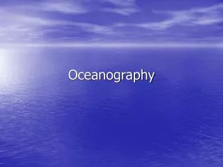
Scattering by spheres • simple shape, well studied • an acoustically small and compact non-spherical body scatters in about the same way as a sphere of same volume and same average physical characteristics (, c) • acoustically small ( ka << 1 ) dimensions much less than those of incident sound wavelength • rigid sphere ka >> 1 reflection dominates, geometrical or specular scattering • rigid sphere ka << 1 diffraction dominates, Rayleigh scattering • fluid sphere – includes transmission through medium Oc679 Acoustical Oceanography
short wavelengths ka >> 1 or big objects geometrical scatter from a rigid sphere ( ka >> 1 ) specular (mirrorlike) reflection in the Kirchoff approximation ( discussed in text) plane waves reflect from an area as if the local, curved surface is a plane scatter consists of a spray of reflected waves each obeying simple reflection law – that is, angle of reflection = angle of incidence – we will employ a ray solution diffraction effects are ignored - these would come from edge of shadow and behind sphere we will calculate the scattering from a fixed, rigid, perfectly reflecting sphere at very high frequencies ( ka >> 1 ) incident sound is a plane wave of intensity Iinc no energy absorption in medium no energy penetrates surface of sphere Oc679 Acoustical Oceanography
short wavelengths ka >> 1 short wavelengths ka >> 1 or big objects adi dSicosi 2asini a i dSi di is a ring increment about the sphere 1st we need to know the incoming power at angle i surface area increment (corresponding to grey shaded area) component in direction of incident wave input power to ring Oc679 Acoustical Oceanography
short wavelengths ka >> 1 short wavelengths ka >> 1 or big objects incident rays within angular increment di at angle i are scattered within increment ds=2di at angle s=2i now, calculate scattered power the geometrically-scattered power measured at range R is assume all incident power is scattered [ no power loss ] then and in terms of scattering length result: scattered intensity is independent of angle of incidence – which should be the case by symmetry of the sphere, but is not the case in general in the case of the sphere, this means that all differential geometrical scattering cross-sections, including backscattering cross-sections, are equal [ we will get back to this later ] Oc679 Acoustical Oceanography
short wavelengths ka >> 1 short wavelengths ka >> 1 or big objects the differential scattering cross-section is: and the total geometrical scattering cross-section is >> >> , where a2 is the cross-sectional area gs does not include the effects of diffraction, so is not the total scattering cross-section the ray solution is deceptively simple: is accurate in the backscatter direction 0-90 but it ignores the complicated interference patterns beyond 90 more complete calculations using wave theory indicate that the total scattering cross-section approaches twice its geometrical cross-section (2a2) for large ka Oc679 Acoustical Oceanography
long wavelengths ka << 1 or small objects Rayleigh scatter from a sphere ka << 1 when the wavelength is large compared to the sphere radius, scatter is due solely to diffraction. 2 simple conditions cause scatter: • monopole radiation – in the case that the bulk elasticity (E1) of the sphere (recall E = pA/ = compressibility-1) is less than that of water (E0), the incident condensations and rarefactions compress and expand the body, thereby reradiating a spherical wave – phase reversed if E1>E0 • dipole radiation – if the sphere’s density (1) is much greater than that of the medium (0), the body’s inertia will cause it to lag behind as the plane wave oscillates (sloshes back and forth). This motion is equivalent to the water being at rest and the body being in oscillation. This motion generates a dipole reradiation. When 1< 0, the effect is the same but the phase is reversed. In general, when 1 0, the scattered pressure is proportional to cos, where is the angle between scattered and incident directions. Oc679 Acoustical Oceanography
long wavelengths ka << 1 long wavelengths ka << 1 or small objects peaks, troughs at ka>1 due to interference between diffracted wave around periphery and wave reflected at front surface of sphere M&C develop a solution for the monopole and dipole radiation independently and then sum them the scattered pressure is: geometrical scattering Rayleigh scattering scattering length and cross-sections determined by referencing R to 1 m backscatter determined by setting = 0 relative scattering cross-section is obtained by /a2 and is (ka)4 result: the acoustical scattering cross-section for Rayleigh scatter is much less than for geometrical scatter because sound waves bend around and are almost unaffected by acoustically small, non-resonant bodies Oc679 Acoustical Oceanography
fluid sphere, Rayleigh scattering ( ka << 1) more general case, when sphere is an elastic fluid • g = 1/0, ratio of sphere’s density to medium density • h = c1/c0 • e = E1/E0 • = angle between incident and scatter directions monopole component dipole component [ backscatter determined for = 0 ] • most bodies in the sea have values of e and g close to unity and both terms are of similar importance • bubbles • have e << 1 and g << 1 - in this case the monopole term dominates • highly compressible bodies such as bubbles are capable of resonating when ka << 1 • - resonant bubbles produce scattering cross-sections several orders of magnitude greater than geometrical Oc679 Acoustical Oceanography
small target compared to λ ka << 1 Rayleigh scattering large target compared to λ ka << 1 geometrical scattering
scattering of light follows essentially the same scattering laws as sound but light wavelengths are much smaller than sound - O(100s of nm) almost all scattering bodies in seawater are large compared to optical wavelengths and have optical cross-sections equal to their geometrical cross-sections the sea is turbid to light on the other hand, acoustic wavelengths are typically large compared to scattering bodies found in seawater (at 300 kHz, 5 mm, 4 orders of magnitude larger) - acoustic scattering is dominated by Rayleigh scattering by comparison the sea is transparent to sound - what limits the propagation of 300 kHz sound is not scattering but absorption Oc679 Acoustical Oceanography
why is the sky blue? Rayleigh scattering α 1/λ4 λblue << λred reds pass through atmosphere without scattering but blues are scattered from O2 molecules and enters our eyes from a range of angles violet scattered even better but our eyes are less sensitive to this sunrise/sunset at low azimuth, light passes through extended range of atmosphere blue completely scattered out and sun appears red green flash occurs at the very end of the sunset (beginning of sunrise, when sun has passed below horizon shorter wavelengths refracted more effectively than longer wavelengths blue has been scattered out, reds are not effectively refracted what’s left if green (sometimes very bright and pops up above horizon for < 1s) Oc679 Acoustical Oceanography
scattering from microstructure hints of scattering from internal waves and microstructure in 60s, 70s but confusing because of bio-scattering alternatively, bio-scattering may be confused with microstructure scattering leading to errors in estimating plankton populations scattering cross-sections were computed based on Tatarski’s computations for atmospheric radar (Proni & Apel 1975) these were based on turbulence structure functions note: these included the effects of velocity fluctuations as well as T (or c) fluctuations but uair/cair >> uwater/cwater
1st experimental evidence from controlled experiments in Wellington reservoir, W. Australia (Thorpe & Brubaker, 1983) “Observations of sound reflection by temperature microstructure” L&O Known sources Towed cylinder and weights at fixed depths from vessel 1 Measured using 102 kHz sounder from vessel 2 • results • no signal when towed in mixed layer – thus velocity fluctuations do not contribute • clear signal of cylinder and weight wakes in stratified regions • estimates of energy dissipated by towed cylinder permitted estimates of turbulence quantities, to which scattering theory could be compared a-a, b-b, c-c are natural scatterers
theories employ the use of robust statistical models of turbulence spectra Batchelor, 1957 (“wave scattering due to turbulence” Proc.Symp.Nav.Hydro.) Goodman, 1990 (considers the bistatic or multistatic problem, not just backscatter) Ross etal 2004
High-frequency acoustics – this is an important tool to help detect instabilities that lead to turbulence scattering from small-scale sound speed fluctuations caused by T and S microstructure sound speed c=c(T,p) Ross and Lueck 2003
Andone Lavery WHOI Lavery etal 2009
here all scattering is bio. note difference in low k spectra which tend to decrease toward low k compared to turbulence spectra
coordinate systems rectangular cylindrical spherical Oc679 Acoustical Oceanography
an object is effectively insonified by plane waves when its dimensions are smaller than the 1st Fresnel zone – within the 1st Fresnel zone, a spherical wavefront can be approximated as a plane wave Oc679 Acoustical Oceanography
Urick definition of volume scattering strength (or backscattering strength if referred to same source and receiver in term of surface scattering can define a surface scattering strength note: the distinction in the definitions – the volume scattering strength Sv is defined by the ratio Iscat/Iinc, each referenced to 1 m (or 1 yd) from the object in M&C terms (that we have so far), Iscat is referenced to the receiver at range R from the object while Iinc referred to 1 m from object– the inclusion of attenuation and spherical spreading (1/R2) gives the length scale unit Oc679 Acoustical Oceanography
Urick fig 8.3 • a more complete schematic of the problem includes beam pattern of single transducer as both source (b) and receiver (b’) ( here absorption ignored ) • I0 is the axial intensity at unit distance (source level SL = 10 logI0) • intensity at 1 m in direction (, ) is I0b(, ) • incident intensity at dV is I0b(, )/r2 • intensity backscattered at P 1 m back toward source is (I0b(, )/r2)SvdV • scattered intensity at source is (I0b(, )/r4)SvdV, whereit is assumed that sound spreads spherically from both source and object dV • receiver will produce voltage (rms) R2(I0b(, )b’(, )/r4)SvdV where R is the receiver sensitivity • total receiver output is V[(R2I0SV /r4) b(, )b’(, )] dV Oc679 Acoustical Oceanography