CR Framework Simulink Clocking
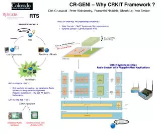
CR Framework Simulink Clocking. WINLAB – Rutgers University Date : July 26 2010 Authors : Prasanthi Maddala , prasanthi.m@gmail.com Khanh Le, kle@winlab.rutgers.edu. CR Framework R3 Architecture. 125 MHz. 100 MHz CE : 4. 100 MHz CE : 4. 25 MHz. 50 MHz. 100 MHz. Clocks

CR Framework Simulink Clocking
E N D
Presentation Transcript
CR Framework Simulink Clocking WINLAB – Rutgers University Date : July 26 2010 Authors : PrasanthiMaddala, prasanthi.m@gmail.com Khanh Le, kle@winlab.rutgers.edu
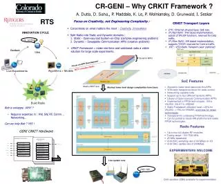
CR Framework R3 Architecture 125 MHz 100 MHz CE : 4 100 MHz CE : 4 25 MHz 50 MHz 100 MHz Clocks Ethernet clock DAC IF clock DAC ref clock ADC IF clock Pkt. Proc. (2) App (2) Control Plane Simulink Clocking Options Clock Enables (Default) Hybrid DCM – Clock Enable Expose Clock Ports Fake Clock Ports (?)
Clock Enables Multiple subsystem generator, with 2 subsystems Can not generate DAC IF and ADC IF clocks. Will more subsystems help - yes, but the generated rtl has to be combined with clk gen. code.
Hybrid DCM - CE Multiple subsystem generator, with 2 subsystems Hybrid DCM – CE generates up to 3 clks. Rest of the clks are clk enabled. 3 highest frequencies are generated using DCM. Can not generate same frequency with both DCM and clock enable Ex: ADC IF clk = 25 MHz. App Clk = 25 MHz - 100 MHz with clock enable Xilinx core FIFOs have to be imported as black boxes (to be used as Sync FIFOs between App and DAC/ADC IFs). Works well if only 3 clocks are required
Expose Clock Ports Need not use Multiple Subsystem generator. Xilinx core FIFOs have to be imported as black boxes (to be used as Sync FIFOs). Generated rtl code has to be combined with a clock generation code to get the bit stream. System clock – 500 MHz (LCM of all the clocks) Easy for Modelsim co-simulation ?