Download

1 / 19
190 likes | 210 Views
Explore the setup of LiDAR technology in simple terrains, understand data implications, and potential analysis for wind energy applications. Analysis of turbine performance using LiDAR data. Conclusions and potential research directions.

E N D
LiDAR analysis at a site with simple terrain Alex Clerc, Lee Cameron Tuesday 2nd September 2014
Contents • Re-cap of TI correction validation study using hub height met masts* • Description of LiDAR setup at a site with simple terrain • Description of LiDAR data • Conclusions and future work *A. Clerc, “Validation Analysis - Turbulence Correction”, PCWG meeting 1/4/2014
Summary of Previous Validation Study (April 2014 PCWG meeting) • Data sets from 23 Power Performance tests re-analysed using PCWG TI correction. • It was found that overall the TI correction is very effective at removing power curve variation, in particular at low and high wind speeds Before TI correction Power [kW] After TI correction TI Specific Energy difference from mean [MWh] Wind Speed [m/s]
Summary of Previous Validation Study (April 2014 PCWG meeting) • Data sets from 23 Power Performance tests re-analysed using PCWG TI correction. • However, at moderate wind speeds (7-10 m/s) power is lower than average at low TI and higher than average for high TI Before TI correction Power [kW] After TI correction TI Specific Energy difference from mean [MWh] Wind Speed [m/s]
Summary of Previous Validation Study (April 2014 PCWG meeting) • For individual turbines, the energy errors due to power curve variation were between +/- 1.5% before the TI correction and +/- 0.7% after the TI correction. • Code to run turbulence correction is on Github, https://github.com/peterdougstuart/PCWG Specific Energy Prediction Error using Inner Range Curve [%]
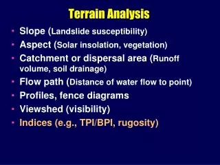
Description of LiDAR experiment • A classic power performance test setup is limited due to having only a few measurement heights, and no information above hub height • Using a LiDAR it is hoped that Rotor Equivalent Wind Speed (REWS)* can be quantified by accounting for: • Horizontal wind speed measured at each height (wind speed profile) • Wind direction measured at each height (veer) • Vertical wind speed measured at each height (inflow angle) *IÑAKI LEZAUN MAS (GAMESA), “Rotor Equivalent Wind Speed”, PCWG Meeting 1/4/2014
Theoretical impact of tilt and inflow • Site assessments and wind flow models focus on the horizontal component of wind speed but turbine rotors are tilted • Theoretical AEP reduction for a rotor tilt of 0°: AEP is independent of inflow angle Actual wind vector Horizontal wind Wind ┴ rotor
Theoretical impact of tilt and inflow • Site assessments and wind flow models focus on the horizontal component of wind speed but turbine rotors are tilted • Theoretical AEP reduction for a rotor tilt of 3°: up to 0.25% loss in AEP per degree inflow Actual wind vector Horizontal wind Wind ┴ rotor
Theoretical impact of tilt and inflow • Site assessments and wind flow models focus on the horizontal component of wind speed but turbine rotors are tilted • Theoretical AEP reduction for a rotor tilt of 6°: up to 0.5% loss in AEP per degree inflow Actual wind vector Horizontal wind Energy lost when wind blows up Wind ┴ rotor Energy gained when wind blows down
Description of LiDAR experiment • Six turbines, two LiDARs. LiDAR 1 (M856) is next to the power performance mast. Height asl LiDAR 2 LiDAR 1
Description of LiDAR measurements • Concurrent LiDAR measurements from June 14 to Aug 14 • At least one measurement height per 20m from turbine lower tip to upper tip • Rotor equivalent wind speed (REWS) is on average lower than hub height (HH) wind speed and has a relationship with turbulence intensity (TI)
Description of LiDAR measurements • Rotor equivalent wind speed (REWS) is on average lower than hub height (HH) wind speed and has a relationship with turbulence intensity (TI) Before TI correction Power [kW] After TI correction Specific Energy difference from mean [MWh] Wind Speed [m/s]
Description of LiDAR measurements • REWS measured by each LiDAR: Table below compares AEP calculations to a base case assumption of hub height wind speed across entire rotor, no veer and inflow = 0 deg.
Description of LiDAR measurements Height asl Most significant difference between two locations is upwind terrain LiDAR 1: wind flows uphill in predominant direction LiDAR 2: wind flows downhill in predominant direction LiDAR 2 Negative inflow angle LiDAR 1 Positive inflow angle
Description of LiDAR measurements • Table below compares to a base case assumption of hub height wind speed across entire rotor, no veer and inflow = 0 deg. *The turbine next to LiDAR 1 underwent a power performance test, so this is inherent in the power performance test result **This implies +0.9% energy available compared to the power performance turbine
Site Calibration • Over the IEC valid sectors (170-230) site calibration ranges from 3% to 5% speed-up at 10m/s. • Site calibration varies considerably with TI; applying power performance TI and shear filters to the site calibration reduces the overall speed-up by 1%. • Complexity of site calibration seems to introduce considerable noise into the analysis
Conclusions • REWS has a strong relationship with turbulence intensity. TI correction should be applied when considering REWS in a power curve correction. • Effectiveness of turbulence intensity correction has been demonstrated in previous presentation*. • https://github.com/peterdougstuart/PCWG • Inflow angle could help explain energy differences between turbines, in this case on a simple site >1% energy difference may be explainable by considering inflow and tilt. • In this example, site calibration seems to be the most difficult problem to solve. Effects of TI, REWS and Inflow angle at this site are much smaller than the effect of the site calibration (5% wind speed). More effort needed on site calibration to improve this analysis. *A. Clerc, “Validation Analysis - Turbulence Correction”, PCWG meeting 1/4/2014
Future work • Include a flexible site calibration module in the Github code • Include veer and inflow consideration in the Github code • Analysis of more LiDAR data will be necessary to know if REWS is effective in correcting power curves. • Better understanding of the assumptions behind warranted power curves would be very helpful, in particular: • Shear above hub height • Veer across the rotor • Inflow angle (generally a range is given, e.g. +/-2deg) • For PCWG Guideline Document discussion…