Download
1 / 45
450 likes | 540 Views
Learn about Entity-Relationship Modeling for database organization, relationships, and attributes representation. Understand ER model concepts, ER diagram notation, and its application to database development. Explore the use of ER data modeling and its importance in database design. This lecture covers topics like entities, attributes, relationships, structural constraints, and more. Discover how ER modeling aids in creating a logical data structure independent of specific DBMS, formalizes user requirements, and eases the transition to database design and implementation. Enhance your knowledge of ER modeling with practical examples and real-world applications in industrial data management.

E N D
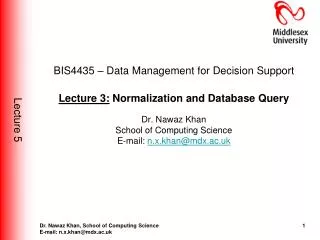
BIS4435 – Industrial Data Management Lecture: Entity-Relationship ModelingDr. Nawaz KhanSchool of Computing ScienceE-mail: n.x.khan@mdx.ac.ukDuty time: Wednesdays : 2:30-4:30 pm
Unit Reading Assignment • Unit 3:Entity Relationship Modelling: A Traditional vs. Object • Oriented Approach • Reading Suggestion: • Connolly, T.M., and Begg, C.E., Database Systems: A Practical • Approach to Design, Implementation and Management, Addison-Wesley, • 4th Edition, ISBN: 0321210255(chapters 11, 13 and 25) • More Reading: Fundamentals of Database Systems. R. Elmasri and S. B. Navathe, 4th Edition, 2004, Addison-Wesley, ISBN 0-321-12226-7 (Chapters 3, 7) BIS4229 – Industrial Data Management Technologies
NOTE: !!!!! • This unit is the basis of the STAGE I CW Portfolio. • In particular, it helps you understand theStructured Query Language (SQL) discussed in unit 4 and Normalisation discussed in unit 5 BIS4229 – Industrial Data Management Technologies
Unit Learning Outcome • At the end of this unit you should be able to: • Analyse cases to identify the entities and their relationships involved • Apply Entity Relationship modelling to represent entities, their relationships and extend it further by identifying attributes for each entity • Transform the model into relationssuitable for Relational database implementation • Identify the need of object oriented approach for semantic data modelling • Apply Unified modelling language to model database objects
Lecture Outline • What is the ER modeling? And why? • Example Database Application (COMPANY) • ER model concepts • Entities and Attributes • Entity Types, Value Sets, and Key Attributes • Relationships and Relationship Types • Weak Entity Types • More about relationships • Structural constraints: cardinality ratio, membership class • Recursive relationships • Subtype and generalization of subtype • ER diagram • Transformation ER model -> relational database schema • EER and UML for data modeling
Entity-Relationship ModelingLab Notes JobList JobID CompanyID JobTitle Salary …. Company CompanyID CompanyName Address ... • CompanyID duplicates in Joblist table: • No: 1-1 relationship • Yes: 1-N relationship (N side: Joblist)
Entity-Relationship ModelingWhat is the ER modeling? And why? • Database approach: • Where is ER modeling?
Entity-Relationship ModelingWhat is the ER modeling? And why? • ER modelling is a logical organisation of data within a database system • ER modelling technique is based on relational data model • Why use ER data modelling: • User requirements can be specified formally & unambiguously • The conceptual data model is independent of any particular DBMS • It does not involve any physical or implemental details • It can be easily understood by ordinary users. • It provides an effective bridge between informal user requirements and logical database design and implementation
Entity-Relationship Modeling Example Database Application (COMPANY) • Requirements of the Company (oversimplified for illustrative purposes) • The company is organized into DEPARTMENTs. Each department has a name, number and an employee who manages the department. We keep track of the start date of the departmentmanager • Each department controls a number of PROJECTs. Each project has a name, number and is located at a single location • We store each EMPLOYEE’s social security number, address, salary, sex, and birthdate. Each employee works for one department but may work on several projects. We keep track of the number of hours per week that an employee currently works on each project. We also keep track of the direct supervisor of each employee • Each employee may have a number of DEPENDENTs. For each dependent, we keep track of their name, sex, birthdate, and relationship to employee
E1 Symbol Meaning ENTITY TYPE WEAK ENTITY TYPE RELATIONSHIP TYPE IDENTIFYING RELATIONSHIP TYPE ATTRIBUTE KEY ATTRIBUTE MULTIVALUED ATTRIBUTE COMPOSITE ATTRIBUTE DERIVED ATTRIBUTE TOTAL PARTICIPATION OF E2 IN R CARDINALITY RATIO 1:N FOR E1:E2 IN R STRUCTURAL CONSTRAINT (min, max) ON PARTICIPATION OF E IN R Summary of ER diagram notation R E2 N R E1 E2 (min,max) R E
Entity-Relationship Modeling ER diagram for the COMPANY database
Entity-Relationship ModelingER model concepts • Entities and Attributes • Entities are specific objects or things in the mini-world that are represented in the database; for example, the EMPLOYEE John Smith, the Research DEPARTMENT, the ProductX PROJECT • Attributes are properties used to describe an entity; for example, an EMPLOYEE entity may have a Name, SSN, Address, Sex, BirthDate • A specific entity will have a value for each of its attributes; for example, a specific employee entity may have Name=‘John Smith’, SSN=‘123456789’, Address=‘731 Fondren, Houston, TX’, Sex=‘M’, BirthDate=‘09-JAN-55’
Entity-Relationship ModelingER model concepts • Types of attributes • Simple: Each entity has a single atomic value for the attribute; for example SSN or Sex • Composite: The attribute may be composed of several components; for example, Address (Apt#, House#, Street, City, State, ZipCode, Country) or Name(FirstName, MiddleName, LastName). Composition may form a hierarchy where some components are themselves composite • Multi-valued: An entity may have multiple values for that attribute; for example, Color of a CAR or PreviousDegrees of a STUDENT. Denoted as {Color} or {PreviousDegrees} • In general, composite and multi-valued attributes may be nested arbitrarily to any number of levels although this is rare. For example, PreviousDegrees of a STUDENT is a composite multi-valued attribute denoted by {PreviousDegrees(College, Year, Degree, Field)}
Entity-Relationship ModelingER model concepts • Entity Types, Value Sets, and Key Attributes • Entities with the same basic attributes are grouped or typed into an entity type. For example, the EMPLOYEE entity type or the PROJECT entity type • An attribute of an entity type for which each entity must have a unique value is called a key attribute of the entity type. For example, SSN of EMPLOYEE • A key attribute may be composite. For example, VehicleTagNumber is a key of the CAR entity type with components (Number, State) • An entity type may have more than one key: choose one arbitrarily as the primary key
Entity-Relationship ModelingER model concepts • Relationships and Relationship Types • A relationship relates two or more distinct entities with a specific meaning; for example, EMPLOYEE John Smith works on the ProductX PROJECT or EMPLOYEE Franklin Wong manages the Research DEPARTMENT • Relationships of the same type are grouped or typed into a relationship type. For example, the WORKS_ON relationship type in which EMPLOYEEs and PROJECTs participate, or the MANAGES relationship type in which EMPLOYEEs and DEPARTMENTs participate • The degree of a relationship type is the number of participating entity types. Both MANAGES and WORKS_ON are binary relationships • More than one relationship type can exist with the same participating entity types; for examples, MANAGES and WORKS_FOR are distinct relationships between EMPLOYEE and DEPARTMENT participate
Entity-Relationship ModelingER model concepts • Weak Entity Types • An entity that does not have a key attribute • A weak entity must participate in an identifying relationship type with an owner or identifying entity type • Entities are identified by the combination of: • A partial key of the weak entity type • The particular entity they are related to in the identifying entity type • Example: a DEPENDENT entity is identified by the dependent’s first name (unique wrt. each EMPLOYEE) andthe specific EMPLOYEE that the dependent is related to. DEPENDENT is a weak entity type with EMPLOYEE as its identifying entity type via the identifying relationship type DEPENDENT_OF
Entity-Relationship Modeling ER diagram for the COMPANY database
Entity-Relationship ModelingMore about relationships • Structural constraints: one way to express semantics of relationship: cardinality ratio and membership class • Cardinality ratio (functionality): It specifies the number of relationship instances that an entity can participate in a binary relationship • one-to-one (1:1) • one-to-many (1:M) or many-to-one (M:1) • many-to-many (M:N) • An example of a 1:1 binary relationship is MANAGES which relates a department entity to the employee who manages that department. This represents the miniworld constraints that an employee can manage only one department and that a department has only one manager • Relationship types of degree 2 are called binary. Relationship types of degree 3 are called ternary and of degree n are called n-ary. In general, an n-ary relationship is not equivalent to n binary relationships (reading suggestion !!)
One-to-many(1:N) or Many-to-one (N:1) RELATIONSHIP EMPLOYEE WORKS_FOR DEPARTMENT e1 e2 e3 e4 e5 e6 e7 r1 r2 r3 r4 r5 r6 r7 d1 d2 d3
MANY-TO-MANY(M:N)RELATIONSHIP EMPLOYEE WORKS_ON PROJECT r9 e1 e2 e3 e4 e5 e6 e7 r1 r2 r3 r4 r5 r6 r7 p1 p2 p3 r8
Entity-Relationship ModelingMore about relationships • Membership class (participation constraint): • Mandatory (total participation) - every instance of a participating entity type must participate in the relationship. Example: ATTEND relationship between STUDENTS and COURSE • Optional (partial participation) - not every instance of a participating entity type must participate in the relationship. Example: OFFER relationship between SCHOOL and MODULE is optional for SCHOOL but mandatory for MODULE • Notation: • Cardinality ratio (of a binary relationship): 1:1, 1:N, N:1, or M:N SHOWN BY PLACING APPROPRIATE NUMBER ON THE LINK • Participation constraint (on each participating entity type): total (called existence dependency) or partial. IN ER DIAGRAMS, TOTAL PARTICIPATION IS DISPLAYED AS A DOUBLE LINE CONNECTING THE PARTICIPATING ENTITY TYPE TO THE RELATIONSHIP, WHEREAS PARTIAL PARTICIPATION IS REPRESENTED BY A SINGLE LINE
Entity-Relationship Modeling ER diagram for the COMPANY database
Entity-Relationship ModelingMore about relationships • Recursive relationships (involuted relationship): relationship among different instances of the same entity
Entity-Relationship ModelingER diagram • An ER model can be expressed in the form of the ER diagram • An entity type is represented by a rectangular box • A relationship is represented by a diamond-shaped box • Relationships are linked to their constituent entity types by arcs • The functionality of a relationship is indicated on the arc • Attributes of entity types/relationships, and membership classes of entity types are listed separately from the diagram • The key attribute(s) is underlined
Entity-Relationship ModelingER diagram • Example: The university database maintains records of its departments, lecturers, course modules, and students • The requirements are summarised as follows: • The university consists of departments. Each department has a unique name and some other descriptive attributes • A department must also have a number of lecturers, one of which is the head of department • All lecturers have different names (we assume so anyway). They must teach one or more modules. A lecturer can only belong to one department • Modules are offered by departments and taught by lecturers. They must also be attended by some students. Each module has a unique module number. • Students must enrol for a number of modules. Each student is given a unique student number.
Entity-Relationship ModelingER diagram • Entity types and their attributes: • DEPARTMENT: DNAME, LOCATION, FACULTY, … • MODULE: MDL-NUMBER, TITLE, TERM, … • STUDENT: SNUMBER,SNAME,ADDRESS,SEX,DOB, … • LECTURER: LNAME, ROOMNUMBER, PHONE, ...
Entity-Relationship ModelingER diagram • Relationships: • HEAD_OF: • 1:1 between LECTURER and DEPARTMENT • Membership: Mandatory for DEPARTMENT • IS_IN: • 1:N between DEPARTMENT and LECTURER • Membership: Mandatory for both • OFFER: • 1:N between DEPARTMENT and MODULE • Membership: Mandatory for MODULE • ENROL: • M:N between STUDENT and MODULE • Membership: Mandatory for both • Attribute: DATE (date of enrolment) • TEACH: • 1:M between LECTURER and MODULE • Membership: Mandatory for both • Do complete the ER Diagram !!
Entity-Relationship ModelingTransformation ER model --> relational database schema • Transformation of entity types • Entity --> Relation • Attribute of entity --> Attribute of relation • Primary key of entity --> Primary key of relation • Transformation of binary relationships - depends on functionality of relationship and membership class of participating entity types
Entity-Relationship ModelingTransformation ER model --> relational database schema • Mandatory membership class • For two entity types E1 and E2: If E2 is a mandatory member of an N:1 (or 1:1) relationship with E1, then the relation for E2 will include the prime attributes of E1 as a foreign key to represent the relationship • For a 1:1 relationship: If the membership class for E1 and E2 are both mandatory, a foreign key can be used in either relation • For an N:1 relationship: If the membership class of E2, which is at the N-side of the relationship, is optional (i.e. partial), then the above guideline is not applicable
Entity-Relationship ModelingTransformation ER model --> relational database schema MODULE DEPARTMENT OFFER 1 N Assume, every module must be offered by a department, then the entity type MODULE is a mandatory member of the relationship OFFER. The relation for MODULE is: MODULE(MDL-NUMBER, TITLE, TERM, ..., DNAME)
Entity-Relationship ModelingTransformation ER model --> relational database schema • Optional membership classes • If entity type E2 is an optional member of the N:1 relationship with entity type E1 (i.e. E2 is at the N-side of the relationship), then the relationship is usually represented by a new relation containing the prime attributes of E1 and E2, together with any attributes of the relationship. The key of the entity type at the N-side (i.e. E2) will become the key of the new relation • If both entity types in a 1:1 relationship have the optional membership, a new relation is created which contains the prime attributes of both entity types, together with any attributes of the relationship. The prime attribute(s) of either entity type will be the key of the new relation.
Entity-Relationship ModelingTransformation ER model --> relational database schema One possible representation of the relationship: BORROWER(BNUMBER, NAME, ADDRESS, ...) BOOK(ISBN, TITLE, ..., BNUMBER) A better alternative: BORROWER(BNUMBER, NAME, ADDRESS, ...) BOOK(ISBN, TITLE, ...) ON_LOAN(ISBN, BNUMBER)
Entity-Relationship ModelingTransformation ER model --> relational database schema • N:M binary relationships: • An N:M relationship is always represented by a new relation which consists of the prime attributes of both participating entity types together with any attributes of the relationship • The combination of the prime attributes will form the primary key of the new relation • Example: ENROL is an M:N relationship between STUDENT and MODULE. To represent the relationship, we have a new relation: ENROL(SNUMBER, MDL-NUMBER, DATE)
Entity-Relationship ModelingTransformation ER model --> relational database schema • Transformation of recursive/involuted relationships: The name(s) of the prime attribute(s) needs to be changed to reflect the role each entity plays in the relationship • Example 1: 1:1 involuted relationship, in which the memberships for both entities are optional PERSON(ID, NAME, ADDRESS, ...) MARRIAGE(HUSBAND-ID, WIFE_ID, DATE_OF_MARRIAGE)
Entity-Relationship ModelingMore about relationships • Recursive relationships (involuted relationship): relationship among different instances of the same entity
Entity-Relationship ModelingTransformation ER model --> relational database schema • Example 2: 1:M involuted relationship. • If the relationship is mandatory or almost mandatory: EMPLOYEE(ID, ENAME, ..., SUPERVISOR_ID) • If the relationship is optional: EMPLOYEE(ID, ENAME, ...) SUPERVISE(ID, START_DATE, ..., SUPERVISOR_ID) • Example 3: N:M involuted relationship PART(PNUMBER, DESCRIPTION, ...) COMPRISE( MAJOR-PNUMBER, MINOR-PNUMBER, QUANTITY)
Entity-Relationship ModelingTransformation ER model --> relational database schema • Transformation of subtypes: • The transformation of a type hierarchy results in a separate relation for the root entity type and each subtype • The key of each relation is the key of the root type • The relation for each subtype also contains its specific attributes in addition to the key • Example: PERSON(ID, NAME, ADDRESS, ...) STUDENT(ID, <attributes specific to students>) LECTURER(ID, <attributes specific to lecturers>) PROFESSOR(ID, <attributes specific to professors>)
Extended E-R Modeling • Generalisation: is a process where an entity is constructed from two or more existing entities based on the similarities they have. For example, an entity Employee is constructed from two entities, Part-Time Employee and Full-Time Employee. Therefore it can be said that the generalisation process is a bottom up approach. • Aggregation: is a process where an entity is constructed from two or more existing entities that are the essential components of the entitiy that is being defined. For example, entity Employee consists of Name, Address and DateOfBirth entities. The Name, Address and DateOfBirth entities are essential components of entity Employee. • Association: is a process where an entity is constructed from the relationships that are defined between two entities. For example, an entity Emplyee-Department is constructed from two entities Employee and Department to show the departments that are assigned to each employee.
Example: EER Modelling Employee Date of Birth Name Employee ID Address Full-time Employee Part-time Employee Monthly salary Hourly Rate salary
EER Modelling: When? The choice of using EER modelling technique depends on the following factors: • some entities share common attributes with others but not with all • an entity type that shares common attributes with others, has very specific relationship and that is unique to that entity type • specific business rules/constraints need to be applied • an entity has an especial relationship with its own instances, in other words when entities demonstrate recursive relationships • if ‘is a’ and ‘has a’ relationships are identified, for example, a Truck is a Vehicle and Truck has a Part.
UML Notations: Class and Association Employee EID Name Address DateOfBirth. CalcHour() CalcAmount() AssignJob(Job) Class Name Attributes Operations AssignJob AssignJob AssignJob Employee Employee Employee * 0..1 1 1..* 0..1 * Job Job Job Class Association
UML Notations: Generalisation employeeType FullTimeEmployee SalaryGrade CalcPension() PartTimeEmployee HourRate CalcWeeklyAmount() Employee EID Name Address DateOfBirth. AssignJob(Job)
UML Notation: Generalisation and Aggregation School 1 1..* 1..* 1..* Course Student employeeType FullTimeEmployee SalaryGrade CalcPension() PartTimeEmployee HourRate CalcWeeklyAmount() Employee EID Name Address DateOfBirth. AssignJob(Job)
Activity Week3 • Draw an ER diagram for a Bank. Each bank can have multiple branches, and each branch can have multiple accounts and loans. • List the entities • Identify PK • What modification you need if you like to include customer in the schema