Collaborative FLCC Experiments
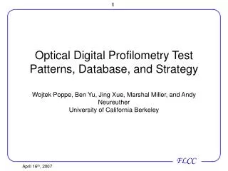
Optical Digital Profilometry Test Patterns, Database, and Strategy Wojtek Poppe, Ben Yu, Jing Xue, Marshal Miller, and Andy Neureuther University of California Berkeley. Collaborative FLCC Experiments. Original Experiments. Optical Digital Profilometry (ODP). FLCC Experiments. FLCC

Collaborative FLCC Experiments
E N D
Presentation Transcript
Optical Digital Profilometry Test Patterns, Database, and StrategyWojtek Poppe, Ben Yu, Jing Xue, Marshal Miller, and Andy NeureutherUniversity of California Berkeley
Collaborative FLCC Experiments Original Experiments Optical Digital Profilometry (ODP) FLCC Experiments FLCC Experiments Designs from industry
Outline • New set of masks from Toppan and experiments at SVTC with the help of ASML • Web accessible database for data aggregation and analysis • Optical Digital Profilometry • New Defocus Test Structures • Measuring Mask Edge Effects • Illumination and 2-D Patterns • Conclusion
New Company New Process Cypress 65nm CMOS Flow SVTC Silicon Valley Technology Center
New Company New Process Cypress 65nm CMOS Flow SVTC Silicon Valley Technology Center
New Company New Process Cypress 65nm CMOS Flow SVTC Silicon Valley Technology Center • Developing new vanilla CMOS flow • No Cypress customizations, so more representative • More synergy and direct benefit for SVTC translates to more wafers
Old Test Chip Layout • Over 15,000 Electrical Test Structures • Six students, six sets of conclusions, one chip 178 30-pad cells Cypress Test Structures
Old Test Chip Layout • Over 15,000 Electrical Test Structures • Six students, six sets of conclusions, one chip 178 30-pad cells Cypress Test Structures
New FLCC06.v2 Chip ODP Etch (Cadence) New Overlay Structures (ASML) ODP Mask Edge (Marshal Miller) ODP litho (Yu Ben) Electrical Test Structures (Magma) • 21 extra 30-pad cell structures (199 total) • 256 gratings for Optical Digital Profilometry (ODP) • Two more students and three companies contributing
4 Layers Per Mask 1mm x 1mm block 9X 8 450um x 220um gratings
4 Layers Per Mask 3mm x 2mm block Wojtek Marshal 48 450um x 220um gratings Yu
Space Available on Dark Field Mask • Atten PSM + 90 degree phase etch • Mosi or Chrome • Glass can have extra 90 degree etch All four layers available Thirty-Two 1mm x 1mm blocks Four 2mm x 3mm blocks
Outline • New set of experiments at SVTC and a new set of masks • Web accessible database for data aggregation and analysis • Optical Digital Profilometry • New Defocus Test Structures • Measuring Mask Edge Effects • Illumination and 2-D Patterns • Conclusion
Tons of Test Structures, Tons of Data, One Chip • Looking at • Systematic CD variation • LWR • Defocus • Enhanced Transistors • Contact hole variation (correlate with pattern noise work) • BSIM model fitting • Oxide thickness and channel doping • Poly corner rounding • Active corner rounding • Non-rectangular transistors • Poly overlap • Electrical Overlay Error • SRAMs and Standard Cells • Poly Etch • Poly CMP • Mask edge effects
Tons of Test Structures, Tons of Data, One Chip • Looking at • Systematic CD variation • LWR • Defocus • ETEC-M validation • Contact hole variation (correlate with pattern noise work) • BSIM model fitting • Oxide thickness and channel doping • Poly corner rounding • Active corner rounding • Non-rectangular transistors • Poly overlap • Electrical Overlay Error • SRAMs and Standard Cells • Poly Etch • Poly CMP • Mask edge effects Data Management Nightmare
Relational Database for Data Aggregation • Over 15,000 transistors, 150 die per wafer, and dozens of wafers • Slice and dice the data in any way • Each data point will be associated with many different tables • Comparing simulation and experiment results • Finding Correlation • Can find correlation between transistors with specific attributes such as proximity or distance from center • Looking at subsets of test structures • Filtering out confounding effects (systematic CD variation) • Platform for Collaboration • Each designer can access and update the database online • Outside people can log on as guests and explore different pattern dependent phenomena
Testing Strategy Data Analysis Reports Store All Possible Data Store Process Conditions Transistor Location Upload process non-idealities Transistor Attributes Measurement Conditions (ex. Temp) Simulation results for different process conditions
Testing Strategy Data Analysis Reports Store All Possible Data Store Process Conditions Transistor Location What else should I look at??? Upload process non-idealities Transistor Attributes Measurement Conditions (ex. Temp) Simulation results for different process conditions
Web Accessible and Centrally Located Probe Station Designers • Upload results for others to see • Update database with calculated process offsets Download test scripts Upload test results • Download data for analysis. • Access any data through SQL queries or pre-built filters • Run some basic statistical analysis Server
Outline • New set of experiments at SVTC and a new set of masks • Web accessible database for data aggregation and analysis • Optical Digital Profilometry • New Defocus Test Structures • Measuring Mask Edge Effects • Illumination and 2-D Patterns • Conclusion
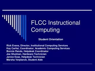
0.35 0.3 0.25 0.2 R, cos,Tan 0.15 0.1 0.05 0 300 350 400 450 500 550 600 650 700 750 wavelength (nm) Upper Film CD Thickness Lower Pitch CD Optical Digital Profilometry LIGHT SOURCE SPECTROMETER The goal of scatterometry is to measure the geometry of fine lines nondestructively with light 100um
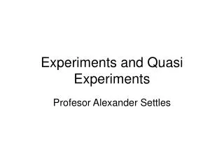
Simulated vs. Measured Results Reflectance Wavelength (nm) Goodness of Fit (GOF) – Indication of best match. 1 is best, 0 is worst. Typical iODP100 GOF > 0.995 Note: Red spectra is simulated and blue is measured
ODP Overview 1 3 2 4 • (n,k) values can be determined on Sopra, or from standard table. • Spectra will be collected on Sopra. Data need to be interpreted in the form that can be read by Timbre ODP TeraGen. • This is what we have from Timbre. • Only for volume production.
Si3N4 SiO2 Si Step 3: The Profile Model
Model Verification Forward Simulation Rigorous Coupled Wave Analysis (RCWA) 1st 0th Incident Light 1st tn for θ、λ
Refelctance Wavelength (nm) Model Verification Forward Simulation Rigorous Coupled Wave Analysis (RCWA) 1st 0th Incident Light 1st tn for θ、λ
Based on the confirmed model (parameter) RCWA simulation generates the library The library is applied to the whole data set to verify its validity Export the library to PAS system for in-line metrology Step 4: Library Generation and Verification
Outline • New set of experiments at SVTC and a new set of masks • Web accessible database for data aggregation and analysis • Optical Digital Profilometry • New Defocus Test Structures • Measuring Mask Edge Effects • Illumination and 2-D Patterns • Conclusion
0o 0o 0o -90o 90o wn d d wb wb Resonant Even Aberration Testing Mask p • Periodic testing pattern, • Probe width provides reference 25% CF magnitude: - Probe phase coherent to even (defocus) aberration - Pattern width equal to minimum feature size - Distance d determines the sensitivity of this aberration and the orthogonality to the other aberrations
Line Spread Function vs. Aberration Spherical Coma Defocus 0.02314 0.05831 0.01817 Reference 0.01451
Resonant Even Aberration Testing Line & point spread function - Inverse Fourier transform of even aberration based on line spread function - Reciprocity of the electric-field spillover
Resonant Even Aberration Testing Sensitivities of defocus and spherical target are at least 28 times larger than the Strehl ratio measurement of aberration at 0.01l aberration
Defocus Monitoring + ODP Calibration? pos- resist neg- resist
Outline • New set of experiments at SVTC and a new set of masks • Web accessible database for data aggregation and analysis • Optical Digital Profilometry • New Defocus Test Structures • Measuring Mask Edge Effects • Illumination and 2-D Patterns • Conclusion
Real CER Imag CEI Mask Edge Effects • Phase Shifting Mask Opening Cross-Talk • Use TEMPEST time-evolution to visualize cross-talk as it occurs among masks openings • Introduced reduced parameter edge and line source models
Simple Mathematical Model for 2nd order Fourier component Ideal thin mask model Edge effects approximated by rectangular box with height unity and width w w x x w is assumed to be small, so the function is approximated as constant x For 50% duty cycle This value are the quantities CER and CER for the real and imaginary correction components
Intuition E Field Mag(E) actual Mag(E) ideal Im(E) Duty Cycle Df Horizontal Shift: CER Vertical Shift: CCEI 50% Re(E) (ideal box) Mag(E) (actual)
Simulation Results Cutline taken far from interface in order to analyze propagating modes
2nd order component of TE mode Period Magnitude Minimum Zero 50% Duty Walls undercut 5 degrees Expect 2nd order to go to zero Vertical Walls
Real CER Imag CEI Simulation Values for CER and CEI
Gratings put on current FLCC mask to explore simulation results Alternating 0o and 180o phase shift regions 4 periods ranging from 3 to 12 l (on mask) Duty cycle ranging from 35-65% 24 different gratings in total Compare data from these gratings to the TEMPEST simulations Experiment: FLCC March ‘07 Mask
Outline • New set of experiments at SVTC and a new set of masks • Web accessible database for data aggregation and analysis • Optical Digital Profilometry • New Defocus Test Structures • Measuring Mask Edge Effects • Illumination and 2-D Patterns • Conclusion
ODP Illumination Test Patterns Normal Incidence Binary Mask Example P = 1.7l/NA Spillover Subtracts Center line not print
ODP Illumination Test Patterns s = 0.59 dipole Binary Mask Example - 180 0 + 180 P = 1.7l/NA Spillover Adds! Center line prints!
ODP Illumination Test Patterns s = 0.59 dipole Binary Mask Example - 180 0 + 180 P = 1.7l/NA • A richer set of combinations are allowed by • Phase-shifted openings • Using spillover from a sizeable 1RU+ programmed focus offset • example P = 1.2l/NA => s = 0.83 dipole