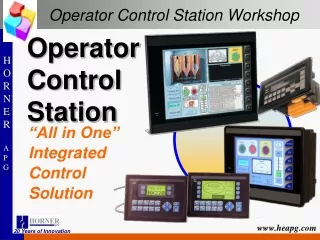
Welcome to Horner Operator Control Station Training
470 likes | 601 Views
Welcome to Horner Operator Control Station Training. - Building Automation Discussion - Product Overview/Capabilities - Controller Basics - Cscape Discussion - Lab1 and Lab2 - More Cscape Discussion - And more labs. Class Agenda. - Scheduled Lighting Control - Zone Settable Schedule

Welcome to Horner Operator Control Station Training
E N D
Presentation Transcript
- Building Automation Discussion - Product Overview/Capabilities - Controller Basics - Cscape Discussion - Lab1 and Lab2 - More Cscape Discussion - And more labs Class Agenda
- Scheduled Lighting Control - Zone Settable Schedule - Motion Sensor for Schedule Override - Temperature Readings - Web Serving (Coming Someday) Horner Building Automation
- Training Room - Only Settable in Training Room - CsCan Lighting Controls - DMX Lighting for CAN Lights Horner Building Automation
- Fully Integrated Display and Keypad - Several Communication Options - Ethernet (Available on Most models) - EGD (Ethernet Global Data) - SRTP - Modbus Client and Server - Ethernet IP - Serial (Modbus, SNP, DF1, etc…) - CsCan Product Features:
- Full Complement of I/O - Analog Inputs - Voltage and Current - Temperature (THM, RTD, and Thermistor) - Analog Output (Voltage and Current) - High Speed Counters - Mixed Modules - Specialty Communication Modules Product Features (cont):
- Various I/O platforms available - Smart Stacks - Remote Fiber I/O - Smart Stix (CsCan) - Smart Mods (Modbus) Product Features (cont):
- Programmable Controller A set of coded instructions that enables a machine to perform a desired sequence of operations. To provide (a machine) with a set of coded working instructions. To train to perform automatically in a desired way. To prepare an instructional sequence - I/O (Inputs / Outputs) Input and Output communication between a controller and its "peripherals". - Program (RLL) Relay Ladder Logic. Similar to a one line electric diagram. - Operator Interface A device to let an operator monitor and adjust parameters on a machine or process through the controller. - Networking Interconnecting Controllers, Operator Interfaces and I/O to allow them all to communicate as one system. Controller Basics
Bit is One Decimal Place (Digital) Either On or Off (1 or 0) A Byte is 8 Bits +127 to -128 Word is 2 Bytes or 16 Bits +32767 to -32768 ex. 00000000 00100101 = +37 (used for Analog and Register values) (sign bit) 16384 8192 4096 2048 1024 512 256 128 64 32 16 8 4 2 1 16 15 14 13 12 11 10 9 8 7 6 5 4 3 2 1 Controller Basics
%I# Field Discrete Input to OCS. (Digital Inputs) %Q# Field Discrete Output from OCS. (Digital Outputs) %M# Internal Coils in OCS. %T# Internal Coils in OCS. Non-Retentive. %S# Internal Diagnostic Contacts. %K# Function Key Contacts. %D# Display bits used to turn on screens and for logical compares. Bit Type I/O Type
%R# Internal 16 bit Registers used to store user data information. Timers, counters, and data storage. %AI# Field varying signal input to OCS. %AQ# Field varying signal output from OCS. %SR# Internal system values like Time/Date/Year, display, number, LED’s and more. Word I/O Type
- Serial - PC w/ Serial Port - USB to RS232 converter (HE500USB600) - Ethernet (Optional on Most Units) - PCI or ISA - USB to CAN Interface (K-CAN) - USB (Currently only on the XL6) CscapeCommunication Options
Up to 255 Com Ports available. Communication Setup (Serial)
3 different modes of Ethernet: GPRS – Cellular NX/QX – Embedded XL Series – Optional Communication Setup (Ethernet)
3 different CAN Interfaces: CGM500 – ISA ESD – PCI K CAN – USB or PCI Communication Setup (CAN)
Configures Internal Modem and Phone Number New in Cscape 8.6 Communication Setup (Modem)
View Properties Dialog Auto-Save Deselect Element Open Last File Export Setpoint Data Aggressive Debug Use Classic Cscape Use Abbreviated Part Numbers Editor Options
View “Properties Dialog” after Snap-in of Element When checked, the programmer will need to assign addresses to the element after placement. The Properties Dialog box will automatically open. Editor Options
Auto-save When checked, this option will automatically save the program at that moment in time. Caution that this feature will not prompt the programmer that an Auto-save is about to take place so take care and archive programs. Return to Editor Options Editor Options
De-select element after placement If checked. After an element is placed on the screen, the arrow pointer will appear. If unchecked, the element will remain active until the arrow is selected from the Tool Bar or ESC is pressed. Return to Editor Options Editor Options
Open last file on startup If checked, Cscape will open the last saved file when Cscape is opened the next time. Return to Editor Options Editor Options
Export Setpoint Data Return to Editor Options Editor Options
Use Aggressive Debug Screen Updates When checked, this option will update your PC’s video card more often than when it is not checked. On some PC’s if not checked, Debug may not indicate the true state of some elements. Return to Editor Options Editor Options
Use Classic Cscape Mode When checked, Cscape will have the same look and feel as pre-version 8.5. Return to Editor Options Editor Options
Use Abbreviated Part Numbers The US and European Offices have different part numbering structure for the same components. When checked, it will display the US part numbers in areas where part numbers are referenced. Editor Options
Multiple Output Coils Function Blocks Variable Display Advanced IEC 61131 Editor Options - Ladder
Multiple Output Coils Allow – Allows programmer to reference the same output coil multiple times without generating an error. Warning – Allows programmer to reference the same output coil multiple times but will generate an error when error checking is performed and when a download is performed. Warning will still allow the programmer to download the program. Error – Will generate an error when error checking is performed and when a download is attempted but will not allow a download. Return to Ladder Editor Options Editor Options - Ladder
Function Blocks When checked, allows programmer to branch around functions with a contact. An error will be generated at the time of a download if this is not checked and a branch around a function is performed. Return to Ladder Editor Options Editor Options - Ladder
Variable Display Name and Address will display both the I/O name assigned to the variable, if assigned, and the address of the variable in Cscape. Address Only will display only the address of the variable in Cscape. Return to Ladder Editor Options Editor Options - Ladder
Advanced IEC 61131 Languages This should be left as “Only Execute Advanced Ladder” Editor Options - Ladder
2 options for laddering numbering: Line Numbers – Black Numbers Rung Numbers – Shown in red after a rung is created. Line numbers count all spaces and comments where the rung number only increases when a rung is created. Editor Options - Numbering
This sets the background color of Cscape. Take caution when using the following colors: Red – Debug is red so debug is difficult to view. Black – Rungs are black so impossible to see rungs. White – Grid lines are white so grid lines are not viewable. Editor Options - Colors
Connect button is used to go online with the controller and offline with the controller when connecting serially to a controller. Pre-version 8.6, the software would capture the configured port when Cscape was opened. Connecting to a Controller
Local indicates the controller ID that the software is directly connected. Target indicates the ID that the software is attempting to communicate with. It is possible to have a Local and Target that are different. Connecting to a Controller
Things to verify if Cscape is not communicating with the controller: - Verify the state of the Local ID. If the local contains ???, then the software is not communicating to the controller. - Verify that another software package is using the port. - Verify that the unit is powered up. - Verify that the connected unit is not using the programming port for another function. If this is the case, then putting the controller into Stop or IDLE mode through the System Menu will open the port for Cscape communication. - If the Local indicates No Port - Verify that the configured port is an actual port on the PC. This can be done through the control panel of the PC. - Verify that the programming cable is plugged into the PC and the controller. - The following is trouble shooting for pass through CsCAN communication. If the Local Indicates a valid number (1 – 253), then verify the Target ID is correct. The state of the Target will be in parenthesis after the Target number. If this indicates anything other R, I, D, then verify the cabling, baud rate, and the setting of the Target node ID. Connecting to a Controller
Rules for I/O Naming: - Names must begin with a letter - Names can not contain any spaces - Names can not contain any special characters (@$%-*) I/O Names
Normally Open Contact – Passes power when element is active. Normally Closed Contact – Passes power when element is not active. Normally Open Coil – Active when rung it true. Normally Closed Coil – Active when the rung is not true. Boolean Elements
Place Contact in the A column. Notice the Screw Terminal in the left margin. Creating New Rung
Right Click in the left margin to create a new rung of logic. Creating New Rung