Download
1 / 28
280 likes | 577 Views
Pneumatic Power FRC Conference 4/27/06. By Raul Olivera. Agenda. Some Basics of Pneumatics and Associated Physics Pressure - Absolute & Gage Force, Pressure & Area Air Properties Flow Rates Electrical Analogy Mechanical Power & Work Pneumatic Energy & Power

E N D
Pneumatic Power FRC Conference 4/27/06 By Raul Olivera
Agenda • Some Basics of Pneumatics and Associated Physics • Pressure - Absolute & Gage • Force, Pressure & Area • Air Properties • Flow Rates • Electrical Analogy • Mechanical Power & Work • Pneumatic Energy & Power • Managing Pneumatic Energy Capacity • Power Experiment • Pneumatics vs. Motors
Pressure - Absolute & Gage • Pressure = matter pushing against matter • Object pushing against another object • Absolute (psia) => True matter based pressure • 0 psia => no matter present to press against objects • Not too important in our designs • Gage (psig) => Relative to Atmosphere • 0 psig => pressure in equilibrium with atmosphere • All regulators and gauges based on this
Force, Pressure & Area • Pressure = Force / Area • Force = Pressure X Area • Example: 30 psig in 2” diameter cylinder Area = pr2 = p(1”)2 = 3.14sq-in 30 psig 94.2 lbs 2.0” dia. Force = 30 psi X 3.14 sq-in = 94.2 lbs
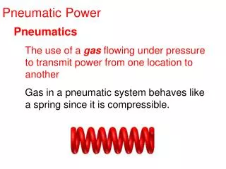
Some Basic Properties of Air • Compressible • Higher Pressure = Higher Friction • Ideal Gas Law: • PV = nRT • Pressure is proportional to Temperature • Pressure is inversely proportional to Volume
Flow Rates • Flow rate = Volume / time • i.e. CFM (L/min, cu-in/sec) • Flow Controls - Valves • Solenoid Value • Check Valve • Relief Valve • Flow Control Valve • Unintended Flow Restrictions: • Narrow Passages • Flow Friction • Pressure drops while it is flowing due to restrictions
Electrical Analogy • Pressure = Voltage • Volume = Capacitance • Flow rate = Current • Flow Restrictions = Resistance • HOWEVER: Air is compressible => more non-linearities than those in electrical systems
Mechanical Power & Work • Work = Force x Distance • Also Work = Torque x Revolutions • Mechanical Energy is always involved in doing work • It is transferred or converted • Power = Work / Time • or Energy / Time • Power Concept • How far an object can be moved in a given time • The power rating of motors is what allows us to determine which ones can be used for a given job • Power rating for pneumatic actuators? • Depends greatly on the rest of the pneumatic system
Pneumatic Energy & Power PEU = Pneumatic Energy Units • Energy = Force x Distance • Force = Pressure x Area • Distance = Volume / Area • Energy = Pressure x Volume ( psig x cu-in => in-lbs ) • Power = Energy / Time • Power = Pressure x Volume / Time ( Units = in-lbs ) • Flow rate = Volume / Time • Power = Pressure x Flow rate ( Psig x cu-in/sec => in-lbs/sec )
Managing Pneumatic Capacity • Pneumatic Energy Capacity = Pressurized Air • Managing the loss and addition of pressurized air is very important WHY - the volume of air used in large cylinders could deplete your supply very quickly if not managed
Managing Pneumatic Energy Capacity • Store Pneumatic Energy • Storage Tanks • Tubing, Fittings & Valves • Compressor • Consume Pneumatic Energy • Exhaust of actuators • Leakage • Add Pneumatic Energy • Activate compressor
Energy Capacity Example 120 psig 60 psig
Managing Pneumatic Energy Capacity • Energy Capacity Example: • Storage Tanks • Volume = 18.85 cu-in (37.7 cu-in for 2 tanks) • Pressure = 120 psig => Energy Capacity = 4524 (2 tanks) • Cylinder - 2” dia x 24” stroke • Volume = 75.4 cu-in • Pressure = 60 psig => Energy Capacity used = 4524 • Conclusion: After 2 extensions and one contraction, the pressure in the tanks drops to less than 20 psig
Energy Capacity Example 120 psig 60 psig
The Compressor • Averages about 660 PEU/s in the cut out range (90 to 120 psig)
Managing Pneumatic Energy Capacity • Energy Capacity Example - AGAIN: • Storage Tanks => Energy Capacity = 4524 (2 tanks) • Cylinder - 2” dia x 24” stroke • Energy Capacity used = 4524 • Compressor can replace 660 per second • Conclusion: It will take 6.85 seconds to replace the energy used by one activation
Managing Pneumatic Energy Capacity • Managing the Loss of Energy • Use only the amount of energy required, not too much more - WHY? • Minimize Volume: • tubing length - valve to cylinder • cylinder stroke • cylinder diameter • Minimize regulated pressure • But, keep above valve pilot pressure requirement
Optimize Cylinder Stroke, Diameter and Pressure • Stroke • Shorter stroke => less leverage for angled movement • Shorter stroke => less weight for cylinder • Diameter • Smaller diameter => more pressure required for same force • Smaller diameter => less weight for cylinder • Pressure • Less pressure => need a bigger, heavier cylinder • Less pressure => less likely to leak
Table Power Experiment • Purpose: Determine Force and Power curves for a pneumatic cylinder • Set-up: • 8” stroke by 1.5” diameter cylinder • All data taken at 60 psig • Time recorded to fully extend or contract (8.0”) • Electronic sensor used at both ends of stroke for timing accuracy Pull Configuration Push Configuration Pulley Cylinder Weight
Pneumatic Power • Force versus time curve was non-linear as expected • Experimental setup was not perfect, some variation in data expected • Some friction in cable system • Ran several times for each weight and took average • Max force that could move was typically less than 85% of theoretical max force
This can be bad, cannot move objects at rated force - design for this This could be good, if leakage occurs and pressure drops slightly, the cylinder will still hold Resisting force Force Exerting force Regulated Pressure Cylinder / System Hysteresis • Actuation hysteresis is very pronounced due to: • Internal cylinder friction • Non-linear behavior of flow through delivery system
Pneumatic Power • This pneumatic cylinder systems is not as powerful as better motors in our KOP • 1.5” cylinder ~= 80 watts • FP motor ~= 171 watts • CIM motor (small) ~= 337 watts • How do we deal with non-linear behavior? • Design for the max force to occur before the “knee” in the curve
Cylinders vs. Motors • Force versus speed curve is linear for DC Motor system; non-linear for the Pneumatic system
Pneumatics vs. DC MotorsSome, but not all important differences • You are allowed to use as many cylinders as you like • However, you are limited in the types and sizes of cylinders allowed • You are limited to the KOP Motors • Most of what you need for the pneumatic system is provided in the KOP or easily ordered • Motors have to be geared to produce the desired forces • Cylinders size can just be picked for the forces you need • Pneumatics are best suited for linear motion • Motors are best suited for angular motion
Pneumatics vs. DC MotorsSome, but not all important differences • Our ability to control the position of mechanisms actuated by cylinders is very limited • We are not given integrated, dynamic airflow or pressure controls • We are given much more versatile electronic controls for motors • Cylinders can be stalled without damage to the pneumatic system • Motors will draw large current and let out the magic smoke • Cylinders absorb shock loads rather well and bounce back • However, be careful of over pressure conditions caused by flow control valves • Motors have to be actively held with feedback controls or locked
Pneumatics vs. DC MotorsSome, but not all important differences • Cylinders use up their power source rather quickly • The 2 air tanks we are allowed do not hold much work capacity • Motors use up very little of the total capacity of the battery • The decision to use Pneumatics • The initial investment in weight is great - mostly due to compressor • Otherwise, very limited air capacity if leave compressor off robot • Once invested use for as many applications as feasible • Easy to add more functionality • Cylinders used with single solenoid valves are great for Armageddon devices - stuff happens when power is shut off • This could be good or bad - use wisely