
Chapter 12
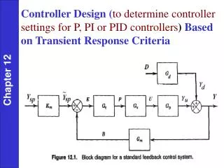
Controller Design ( to determine controller settings for P, PI or PID controllers ) Based on Transient Response Criteria. Chapter 12. Desirable Controller Features The closed-loop system must be stable. The effects of disturbances are minimized, i.e., good disturbance rejection.

Chapter 12
E N D
Presentation Transcript
Controller Design (todetermine controller settings for P, PI or PID controllers) Based on Transient Response Criteria Chapter 12
Desirable Controller Features • The closed-loop system must be stable. • The effects of disturbances are minimized, i.e., good disturbance rejection. • Quick and smooth responses to the set-point changes are guaranteed, i.e., good set-point tracking. • Off-set is eliminated. • Excessive controller action is avoided. • The control system is robust, i.e., it is insensitive to changes in operating conditions and to inaccuracies in process model and/or measurements. Chapter 12
Simplified Block Diagram D(s) B(s) P(s)
Alternatives for Controller Design • Direct synthesis (DS) method • Internal model control (IMC) method • Controller tuning relations • Frequency response techniques • Computer simulation • On-line tuning after the control system is installed. Chapter 12
Direct Synthesis Steps • Specify desired closed-loop response (transfer function) • Assume process model • Solve for controller transfer function
Example 12.1 Use the DS design method to calculate PID controller settings for the process: Chapter 12
Consider three values of the desired closed-loop time constant: . Evaluate the controllers for unit step changes in both the set point and the disturbance, assuming that Gd = G. Repeat the evaluation for two cases: • The process model is perfect ( = G). • The model gain is = 0.9, instead of the actual value, K = 2. Thus, Chapter 12 The controller settings for this example are:
Chapter 12 Figure 12.3 Simulation results for Example 12.1 (a): correct model gain.
Simulation results for Example 21.1(b): incorrect model gain.
PID Controller Design Procedure Based on IMC Method –Step 1: factor process model
PID Controller Design Procedure Based on IMC Method –Step 2: derive IMC transfer function
PID Controller Design Procedure Based on IMC Method –Step 3: derive PID transfer function
Controller Synthesis Criteria in Time Domain Time-domain techniques can be classified into two groups: (a) Criteria based on a few points in the response (b) Criteria based on the entire response, or integral criteria
Approach (a) Based on settling time, % overshoot, rise time, decay ratio (Fig. 5.10 can be viewed as closed-loop response). Several methods based on 1/4 decay ratio have been proposed, e.g., Cohen-Coon and Ziegler-Nichols.
Approach (b) - Criteria • Integral of absolute value of error (IAE) • Integral of square error (ISE) • Time-weighted IAE (ITAE)
Approach (b) - Remarks Pick controller parameters to minimize integral. • IAE allows larger overall deviation than ISE (with smaller overshoots). • ISE needs longer settling time • ITAE weights errors occurring later more heavily Approximate optimum tuning parameters are correlated with K, , (Table 12.3).


