Preproduction Status & Results
80 likes | 206 Views
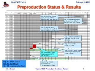
Preproduction Status & Results. Qty. 4 completed thermal cycle, burn-in and final electrical test, Sent to SLAC. Qty. 10 completed thermal cycle, burn-in and final electrical test, Sent to INFN. Qty. 14 thermal cycle complete, burn-in and final electrical test (ECD 2/12/04).

Preproduction Status & Results
E N D
Presentation Transcript
Preproduction Status & Results Qty. 4 completed thermal cycle, burn-in and final electrical test, Sent to SLAC Qty. 10 completed thermal cycle, burn-in and final electrical test, Sent to INFN Qty. 14 thermal cycle complete, burn-in and final electrical test (ECD 2/12/04) Qty. 6 pre-encap electrical test (ship to SLAC ECD 2/13/04) Qty. 3 wire bonding (ECD 2-13-04) Qty. 4 “Short” TMCM, install pitch adaptor & SMT parts (ECD 2/20/04) Qty. 2 samples of Pitch Adaptor sent to INFN Qty. 4 Scrap Qty. 40 short TMCM Qty. 10 tall TMCM Qty. 50 preproduction total Qty. 10 “Tall TMCM” (ECD 2/24/04) +2 spare parts on hand
Pre-Encapsulation Test Results Example Pre-Encapsulation Test Session • Results from the most recent test session at Teledyne, SN 173, 359, 509, 516, 523, 524, 562, 571, 576, 578, 584, 593. • SN 523: • One GTFE chip had a broken calibration mask and drew excess current. It was the only chip out of 312 that had to be replaced. • SN 516: • One wire bond lifted on a GTFE address line. • Shorts cleared on the pitch adapter between two pairs of channels. • SN 516 • Passed the electrical test, but with 2 shorted channels. Inspection of that region uncovered damaged wire bonds that had to be repaired. • SN 509 • Passed the electrical test, but with 2 shorted channels. Debris could be seen between the two traces and was cleaned out. • These 4 were reworked and tested perfect the following day. • The other 8 were perfect in the initial test.
Failed ASICs • The incidence of ASIC failure, requiring reworking of MCMs, is low enough that we can live with it, but… • All chips were fully tested on the wafer before dicing, so in principle we should not find any failures. • Damage during lapping, dicing, picking, inspection? • Damage during MCM assembly? • We are starting a program to isolate the problem by probing • Failed dice returned from Teledyne. • Fresh dice from GDSI. New vacuum fixture to be used for probe testing loose GTFE chips.
Preproduction Electrical Results • So far, no MCMs have failed at • Post encapsulation/conformal coat test at Teledyne. • 3-temperature test following thermal cycling at SLAC. • Burn-in. • Final test after burn-in. • In fact, the number of bad channels has not increased at any of those test points with respect to the pre-encapsulation test. • Of 4 MCMs checked so far by probing, none has even a single broken trace or wire bond at the channel inputs. • Note that we have yet not seen any chips go bad on MCMs following encapsulation and final test, in the Mini-Tower or preproduction. • This is evidence that the chips are robust when protected from physical damage and that the ASIC failures seen during pre-encapsulation testing are not results of infant mortality.
Measures on MCM Board B-B’ C-C’ A-A’
P1 P2 P3 P4 P5 Planarity on MCM Board
Planarity of the Strips 100um 200um A0 A2 A3 A4 A5
Conclusions • The MCM assembly procedure is able to deliver boards that meet all electrical requirements, generally with much less than the maximum of 8 bad channels per MCM. • Some rework is required after wire bonding and before encapsulation. • The incidence of bad dice is low and seems to be decreasing. • We will do some work to understand whether chips are damaged during lapping, dicing, picking, and inspection at GDSI. • The largest amount of rework results from physical damage to wire bonds during handling. New fixtures will be made to reduce this. • The finished MCMs conform to the designed height and straightness of the top edge, where G&A will wire bond. • The perpendicularity of the top edge may be improved with a new fixture, but G&A is confident that it is adequate for good quality wire bonds to the SSDs (but possibly at a cost in wire bonding time).